The formula for a full-tilt, max-attack assault on a Street class in a Corvette is pretty well known. Modifications are severely limited by the rules. The four key areas are 1) a stiffer front sway bar to improve transient response and limit camber loss in roll, 2) an alignment with increased tire static negative camber to produce more grip at the cornering limit, 3) sticky, autocross-specific, fast-heating, quick-responding, fast-wearing, too-fat-for-the-rims tires to produce more longitudinal and lateral grip from the first turn, and 4) pimp, double-adjustable shock absorbers, properly valved for autocross to produce the least amount of tire patch force variation considering the bumpy surfaces we race on and, specific to Street class, to act dynamically as springs to supplement the insufficient spring rates provided by the manufacturer. The first three mods are relatively simple. The last one not so much.
One other modification that I initially assumed would be required is a second set of custom, lighter wheels, 18″ diameter all around, mainly to allow a shorter rear tire to improve the gear ratio for better acceleration in 2nd gear. I discovered an issue with this plan, however, which I’ll discuss further down.
I started with Sam Strano’s 1-5/16″ diameter front sway bar with adjustable end-links. It has a choice of two holes in each end, which give you three possible levels of stiffness: both first holes, one first hole and one second hole, and both second holes. I bolted it up with the stiffest setting to begin with and it feels great so far on the street.
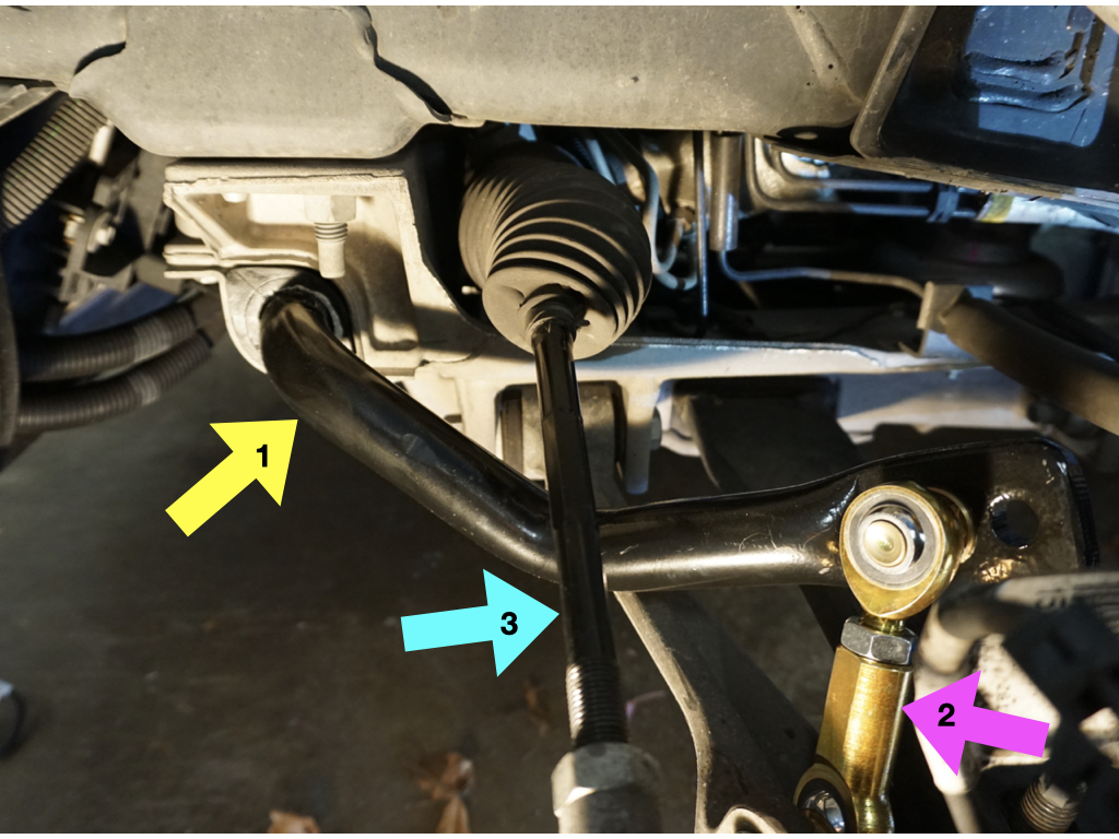
In the picture above the yellow number 1 arrow is pointing to the new front sway bar. At the very end of the bar you can see the unused hole which would produce reduced roll stiffness if the drop-link were located there. Magenta arrow 2 points to the adjustable-length drop-link. At the bottom end you can see some of its spherical ball-joint. Cyan arrow 3 points to the steering tie-rod where the flats are formed that you can count as you turn it to adjust toe.
Next I increased the negative camber at all four corners to the max and reset the toe-in to near zero at the front and 1/4″ (total) at the rear. I was able to do this in my own garage and got about 3 degrees in front and around 1.75 degrees in the rear. (These are approximate as my camber gage doesn’t fit these wheels very well.)
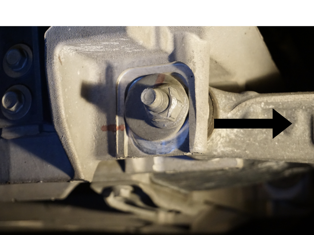
The car had a stock alignment not long ago and I found paint marks that indicated nothing had slipped, so I assumed things were still straight and even from side to side. See the red paint marks in the picture above. The black arrow indicates the direction the lower control arm moves when increasing camber. The eccentric rotated about 90 degrees to get to the place where it wouldn’t go any farther.
Going for max camber at all four corners is simple and straight-forward on the C6. Turn the eccentrics to the stops. You get what you get and don’t worry if one side has a little more than the other. It will happen. You won’t notice. You do want all that Chevy gave you.
Then I use toe plates to get the wheels pointed back straight. Going from half a degree of negative camber to around 3 degrees in the front produces a massive amount of toe-in as a by-product. I counted the flats when turning the 6-sided toe-link, putting the same changes into both sides, until the total toe-in was near zero. Same for the rear, except it got massive toe-out from the camber change. At some point I’ll take it to Brad at Clem Tire and have it set more precisely, once I decide on what I want after some testing.

By the way, you don’t have to worry about the caster angle in the front. It will go where it’s gonna go. Let it be, let it be.
For tires I went with Falken RT-660 200TW, 275/35-18 in the front on the stock 8.5″ wide rim and 305/30-19 on the stock 10″ wide rim in the rear. They were here within a few days from Tirerack, but I waited until the weather warmed up a little before having them mounted. Luke at Wheelfixit was kind enough to store them in the middle of his heated shop, in line with the heater output, to make sure they were toasty prior to mounting.
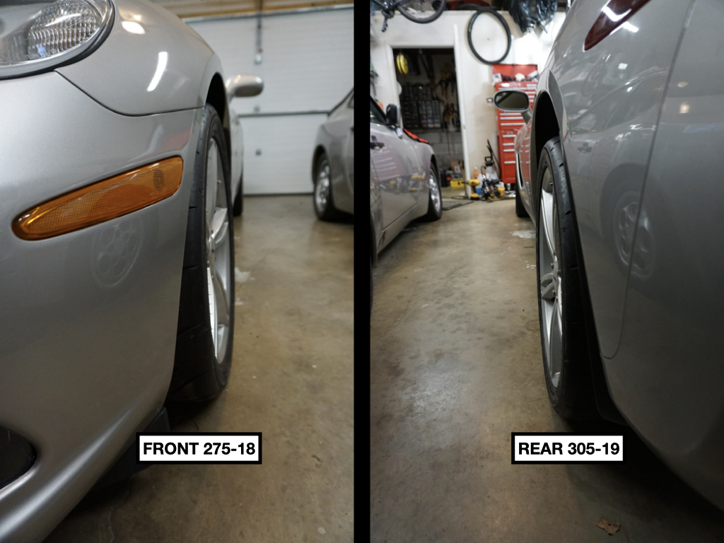
The 305s in the rear are 26.3″ diameter which is a little shorter than the stock 26.9″ tire. The car goes about 72mph in 2nd with the 305, which is still a little too fast. 69-70mph is considered more perfect.* I could have gone with a 315, but I wasn’t able to positively conclude it would fit without rubbing given the narrow body of the base C6. (It’s appears to be a close thing.) The standard lower rim range for both of these tires is 10.5″ so pinching them onto a 10″ rim is not particularly radical. The 315 may be an option for the future if I’m having trouble putting power down. It’s only 0.2″ bigger in diameter so it won’t hurt the gearing very much though that’s moving in the wrong direction.
On the other hand, there’s a 315/30 in 18″ which is only 25.5″ in diameter, producing a significant gearing and unsprung weight improvement but will require a custom rim. My plan was to see how the 305 does early in the season and then make the decision whether to obtain a new set of wheels. Then I stumbled into a glitch in the matrix.
The glitch is that there may be no suitable front tire to match to this 315/30-18 rear. I have it on good authority that the front tires needs to be at least 1% smaller diameter than the rears in order to not upset the antilock brake system. (Forget about traction control and stability control… those will be turned off anyway.) The 275/35-18 is slightly taller than the 315/30-18 rear, so it’s out, and the 265/35-18, which would otherwise probably be acceptable, is 25.4″ diameter, which is only 0.4% smaller, less than the supposedly necessary 1%. Concurrently I found a confirming report from a well-known tuner with the same year Corvette who mounted 4 tires of identical size on 4 identical wheels and the ABS tried to kill him and his wife on the track by locking up the rear tires anytime more than 1G of braking was attempted. Will that happen at autocross speeds with a front tire 0.4% smaller than the rear? Dunno, but I hesitate to risk thousands on custom wheels that will be difficult to resell only to have that sort of problem.
With my C5 the front to rear tire size delta was not an issue. I raced for years with the front tire larger in diameter than the rear. As long as the other nannies were turned off the ABS had no issue. That was a different Bosch system as compared to the later Delphi.
So, I’ll see how the 305s do. This car accelerates so ferociously in 2nd gear I really don’t know if a smaller rear tire will even be useful. It could just make the car harder to drive for this old man.
Now we come to the shocks. At present I’ve mounted my old Koni 3013s. These are pretty good performing rebound-adjustable shocks, though the damping curve shapes and force values are not much like what I am specifying to Penske for the 8300-series double-adjustables I’ve ordered.

So, what exact shock characteristics am I specifying? Um, sorry, but I’m not telling.
If I have any competitive advantage over my competition it may be all the research I’ve done into shock absorbers over the last few years. You can find much of it published elsewhere in this blog.
I will describe the process, however. Just not the exact choices I made.
Step 1: The first thing I did when I got the new car was measure the motion ratios for the shocks and the leaf springs. I found a couple of people on-line that had done the measurements. They didn’t agree very closely and they didn’t provide enough information to determine if one or the other had measured correctly or incorrectly. I had to do it myself. If the MRs are not right you might as well buy an off-the-shelf fitment from one of the usual suspects and twiddle with the knobs.
Step 2: The next thing to do, once I had the tires mounted (and the tire/wheel combos weighed), the new FSB in place and the Konis installed, was to weigh the car on a set of scales (borrowed from Tom at the Little Raceshop of Horrors) and get the corner weights. The car weighs 3206lbs with 3/8 fuel and the targa top in place and has 52% of that weight on the front. The cross-weights are quite good and get better with a nice plump driver in the seat.
Step 3: Get numbers for front and rear unsprung weights. These weights are going to be subtracted from the corner weights in the on-line calculator, which mostly uses the front and rear sprung weights in order to calculate system natural frequencies, which is how the suspension stiffness of a car is actually measured. About half of the unsprung weight is simply the wheel/tire combo, so that always gives you a good, easily measured, starting point. I was able to find discreet weights for things like brake disks, calipers, hubs and suspension arms, etc. and come up with pretty good numbers without having to disassemble and weigh each piece of the suspension myself. That’s one nice advantage of operating a car popular with enthusiasts. Some of this work has already been done and is available on the internet.
Step 4: Find the spring rates for the front and rear leaf springs. The internet is your friend. However, there’s a teeny-tiny issue, which I’ll describe in the next step.
Step 5: Now you can go online to Dennis Grant’s Autocross To Win website and find his Dynamics Calculator and start entering numbers. Except, and here’s the teeny-tiny issue, the Corvette suspension design is incompatible with his calculator because it’s not a coil-over design. The Corvette has FRP transverse leaf springs that do not act at the shock mount location as does the more common coil spring wrapped around the shock or strut.
What I had to do was to mathematically transfer the spring force to the shock mount locations while correcting for the shock angles. (For once, a mechanical engineering background paid dividends.) Of course, the front is very different from the rear and must be figured separately. Then I could trick that bastard calculator by entering modified front and rear spring rates. It never knew what hit it.
Step 6: So far this is all pretty cookbook (except maybe for modifying the spring rates) but now you have to insert some knowledge, hunches, guesses, or whatever you got. You must decide how much damping you want in terms of what percentage of critical damping (65%?, 75%?, 95%?, 120%?) and what damping curve shapes and knee locations you want to specify. Will you use regressive, linear or digressive shaped curves, or mixes of each, and then choose the corresponding main piston designs? And how do you want to split the total damping up between compression and rebound? In most shocks they are not anywhere close to equal and it is not clear at all that what road-race teams do is particularly applicable to autocross. The author of The Shock Handbook questioned various people in the automobile industry as to why they used the split they did between compression and rebound and got no sentient answers. DG’s calculator seems to provide a 2 to 1 ratio, that is, twice as much rebound as compression, which is common. (I’ve used that before with excellent results.) I’ve seen some custom-valved shocks with 4 to 1 ratios. This was common in the 1960’s until Jan Zuidijk at Koni Racing (later the founder of JRZ Suspension Engineering) showed the world that it wasn’t fast and put Koni on the racing map. To make things more complicated, if the compression curve is digressive and the rebound linear, a ratio split doesn’t really make sense. You are forced to decide on a ratio at only one shaft velocity and the ratio will be less on one side and climb rapidly on the other. Many road-race teams these days split it evenly between compression and rebound and a few even bias toward compression, sort of like in the graph below. Almost all use velocity histograms during practice sessions to fine tune for each different track.

The shock dyno graph shown above is for the Ohlins shocks I had on the front of the C5. The people that valved it gave me pretty much exactly what I asked for, but I didn’t actually know what to ask for back then!
Note that the compression values (upper half) have distinct “knees” at 1 in/s shaft velocity. Beyond the knees the curves flatten out and rise much more slowly. This is a “digressive” curve shape.
The rebound curves (lower half) are linear, i.e. basically a straight line. You can see that at 1 in/s the compression values are higher than rebound. (Not good.) By 8 in/s the rebound values are higher. (Not good either.)
I chose a knee velocity I like and altered the results from Dennis Grant’s calculator to split it up at my own custom ratio that I think is more suitable for a Street-class car. Then I gave the numbers as targets to Penske.
There is no one and no analysis that can tell you the for-sure answer about how much total damping you should have or compression to rebound damping ratios, especially for this weird sport of autocross where we race on all sorts of strange surfaces in all sorts of conditions. There are many people with many different opinions who will be glad to tell you what they think, especially if you buy from them. I have my own opinions, but I’m not going to reveal exactly what I decided. We will just have to wait and see how it works out. I am happy to say that Steve Horn at Penske was a great pleasure to interface with throughout the process of working through the shock specifications and options, not least of which was making sure the resulting dimensions would be legal per SCCA Street-class rules. He was invariable polite. Not once did he tell me I was nuts.
*Edit: I was recently informed that 69-70mph would be too slow (causing me to run out of gear early) given the rate at which this car can accelerate and that 72 is actually more perfect. Always better to be lucky than good!

The actual link to the calculator is here: http://farnorthracing.com/autocross_secrets16.html
You’re correct that the calculator assumes coaxial springs and shocks. My Excel version breaks out spring motion ratio from shock motion ratio, but it looks like I got lazy with the Javascript version and omitted that feature.
The C5 could use coaxial springs and toss out the leafs, which is handy for tuning spring rates.
The calculator works out bump by doing the design damping ratio as if the body was fixed and the unsprung weight was sprung – it basically turns the car upside-down. Beautiful, elegant theory.
And it doesn’t work. Bummer.
It kicks out a value that is just a little bit too soft. It’s basically the lower bound for what bump could be. Take whatever number it returns and add 10% and you get a much better starting value. I thought I had added that fudge factor to the calculator, but looking at the code I did not.
Maybe I’ll do that later.
65% critical in rebound (+/- a couple of percent) is a proven value that can be taken to the bank. Lots of research by multiple people have proven that one out. Bump is a slipperier fish. But the common practice is to set rebound then tune bump live by symmetricalizing the suspension speed histograms so there’s less pressure to calculate it.
You want to be reaaally careful about where the knee happens, as you really don’t want it to happen in speed ranges generated by car dynamic movements – err on the side of late, rather than early. Your suspension velocity traces will tell the true story, but 1 in/sec seems too early. Super smooth tracks can get away with no knee at all (lots of legacy Bilstein circle track damping is linear to infinity) and I don’t think there’s much (if any) advantage to try and push the knee point closer to the origin. That would be worth testing though.
You are quite right that there are a ton of shock Super Tunas out there peddling bullshit, even decades after A2W was published. I had this shit figured out in 2003, and yet how many cars at nationals 2022 had suspension position sensors?
LikeLike
DG: I really appreciate you putting all this in a comment. You had mentioned much of this to me via email, but I did not want to put it into a post without permission.
LikeLike
Thanks for this information!
May I ask where you set the Koni rebound for the C6?
LikeLike
In the end I had the rebound set not quite at maximum in competition and near full soft for the street.
LikeLike