3 Ways To Take A 180

The course at our last event of the season had an interesting more-than-180 degree sweeping turnaround. Partly by design and partly by not being overly consistent I got data on three different approaches to the corner.

The three afternoon runs are shown in Figure 1, below. Run 1 is green, run 2 is blue and run 3 is red. The day was sunny but cool. The tires definitely got better (warmer) from 1 to 3, which partially determined the changing approaches, but I had already planned to use this corner as a data-analysis opportunity.

figs.001

Figure 1  Turn-around

Here was the plan: Run 1, green, was to be the “momentum maintenance” line. Green would enter the corner beyond cone A faster, via less braking, attempting to carry more speed from the fast section that preceded, even though it would mean a bigger turning arc beyond cone A. Green would continue turning right about half-way down to B to get a good angle when turning back on that cone, again braking as little as possible.

Beyond B Green would take a wider path to get the best possible angle on cone D, not worrying about keeping close to cone C. A good angle on cone D would allow early power application for the following acceleration zone.

Run 2, Blue, was intended to make maximum use of the short acceleration zone between A and B. To do this, the plan was to execute a little more braking on the approach to A and open the steering wheel earlier for the earliest possible application of power. Blue would accelerate for as long as possible and sacrifice some angle on cone B, accepting that the car will go deeper beyond B.

Going deeper beyond B was not necessarily such a bad thing as it would allow a good angle on cone D, just like Green.
Run 3, Red, was planned to be the tightest, minimum distance path from B to D. Red would slow enough before A to allow some acceleration down to B and then get wide enough to cut in at B to cross from B to D by a tight path that was close to cone C.

Cutting a shallow, fast line across from the two cones that form the entrance and exit to a 180 degree turnaround is a strategy I’ve used on larger 180’s at certain national events. It’s only good if the exit cone is not constrained by needing to be backsided. That is, the line must be open beyond that cone so that significant braking for that cone is not required. This was not the case for this particular section.

Which path do you think saved the most time? Or, would you have done something different? Before you decide, I’ll give you some data to think about.

The relative path distances: From A to E the green path is 439 feet, Blue is 428 feet and Red is 425 feet. So, Red was the shortest path, but only by three feet as compared to Blue. As expected, Green was the longest path, 11 feet farther than Blue, 14 feet farther than Red.
Entry speeds: At A, Green is moving 41.6mph, having braked less per the plan. Blue is at 38.1 and Red is at 39.8. There’s no real reason for Blue to be slower than Red. Chalk it up to driver inconsistency and maybe cooler tires.

Maximum speeds between A and B: 41.7mph for Green, i.e. essentially no difference from the entry speed. This makes sense because Green is supposed to be turning smoothly at max lateral g at all times.

Red has managed to accelerate a bit from 39.8 to 42.3mph.

Blue, which had the slowest entry at 38.1mph, gets up to the fastest at 43.9mph, as intended. Of course, if Blue had entered as fast as Red it would have reached an even higher speed.

The path distances and speeds indicate to me that the three runs were driven basically according to plan. The only anomaly is that Red’s entrance speed is a little faster than Blue when it should be, by all rights, a little slower. I was probably driving more aggressively on the warmer times for the Red run. This gives an unfair edge to Red.

So, what actually happened as far as time lost or saved? The Delta-T chart tells the tale in Figure 2, below.

figs.002

Figure 2  Delta-Time

Now, Red was the fastest run overall, so the software has set it as the baseline. It’s a completely flat line. The time difference for the other two runs appear as lines that waver around the red line. When the Green and Blue lines are descending they’re gaining time on Red. When ascending they’re losing time to Red.
From Position 290 to 460 Blue has saved 0.16s over Red. Red has saved 0.08s as compared to Green. But, as you can see, it’s not quite that simple.

Green is catching Red as the data ends and by the time the cars get to the next cone (not shown) Green equals Red. Why? Because the better angle that Green had on cone D allows it to pass D faster and maintain a speed advantage over Red from then on. Blue maintains an advantage over Green, however, having rounded cone D just about as well.

To fully understand what happened we need to separate the story into two parts: before B and after B.

Before B, at Position 360, Blue has pulled a lead of 0.19s on Red. Green initially had a speed advantage on Red and Blue around the cone at B as seen at Position 300, but then loses it due to a longer path and inability to maintain that speed. The relative speeds can be seen in Figure 3, below.

figs.003

Figure 3  Speed

Paradoxically, Green catches Red by Position Index 360. (See Figure 2) It does this by braking less than both Blue and Red as the cone at B is approached. This is the great advantage of the momentum-maintenance mindset: you can really focus on carrying speed and staying off the brakes, which spurs you to take corners faster than you think you can.

Beyond Position 360 we have a give-it-up-to-gain-later situation. Red, the tight path, initially makes up tremendous ground on both Green and Blue, leading Green by 0.29s at Position 410 (and even slightly leading Blue), by virtue of the shorter path, a higher minimum cornering speed (about position 370 in Figure 3) and by a consistently higher speed from 370 to 400.

Red loses everything by cone D, however, having to slow tremendously to get tightly around that cone. Even with slowing a full 6 mph as compared to Blue at D, Red still pushes out a little wider than optimum, pulling a 1.34 lateral g shock at D in an attempt to limit the damage, as seen in the Lateral-g chart in Figure 4, below.

figs.004

Figure 4  Lateral g

Red is royally screwed for the entire next section of the course and both Green and Blue claw back most of the advantage they had previously at Position 360.

Conclusions
1.Maximizing the acceleration and speed from A to B as done by Blue was a good strategy, especially for a relatively powerful car.

2. The big hump in Blue’s delta-T trace centered at Position 410 in Figure 2, indicates that Reds strategy of a flat, fast path across the 180 turn was equal to Blue’s line in the 180 itself. Blue had gained earlier and Blue maintains that lead after cone D, so Red was not the optimum line overall, but might have been if the next feature after cone D had not been as constraining.

3. Given that this feature required more than 180 degrees of turning, ignoring the cone at C and taking a wider path from B to D was necessary to get a proper angle on cone D. This allowed early acceleration from a higher starting speed as the course straightened. Even though Red had warmer tires and was able to accelerate harder than both Green and Blue, it couldn’t catch up beyond cone D. This was a true (and rare) instance of the value of a “late-apex” in the road-race sense thanks to a severely decreasing radius path dumping into an acceleration zone.

How Lowering Affects Your Autocross Car

Part 1- Estimating the Effect on Weight Transfer and Roll 

944-rake.jpg

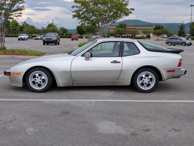
I’m setting up a 1989 Porsche 944 with the sport suspension (Porsche option code M030) for street-class autocross. This suspension design, MacPherson strut in front with threaded spring perches and semi-trailing arm in the rear with indexable torsion bars, allows me to adjust the ride height of the car, i.e. I can lower it from stock. Figure 1 shows the front suspension, looking from the front.

DSC00303

Figure 1

Adjusting the front couldn’t be easier… just twist the spring perch. It’s right there at the base of the spring in the photograph.

Adjusting the rear is the opposite of easy. It’s so horrifying to contemplate that I really don’t want to talk about it. At least it can be done, which is an advantage this car has over many others.

Right now I’m in the middle of swapping M030 torsion bars for stock and re-indexing them, along with renewing all the bushings. I’m aiming at 1” lower than stock as the base setting. The car has a separate method for adjusting it slightly from the base position apart from indexing the bars. That method is intended mainly for corner balancing.

Before I go crazy with lowering the car I want to estimate how much cornering power I can expect to gain compared to the stock ride height and balance that advantage against certain disadvantages that will occur.

One thing people forget is that being able to quickly estimate an answer is just as important as being able to grind out a precise figure. For one thing, maybe the estimate is enough to tell you you’re going down a blind alley. For another, it allows you to know when your precise answer is obviously wrong because you made an error somewhere. (If I only had a nickel for every time a young engineer believed that his obviously (to me) wrong answer just has to be correct because, well, it just has to be because he spent so much time on it and it was derived exactly from first principles as taught in school. Usually, they come back with “I found a slight mistake… how did you know?”)

If anyone can show me where this information is already available for the 944, I’d sure like to see it! And, if you have better numbers than what I’ll be using, I’d love to have those too.

Lowering a 944 (and just about any other car) does two good things: 1) it creates an increase in the maximum available static negative camber, which is limited to much less than optimum for autocross in most cars as they come from the factory, and, 2) it reduces lateral weight transfer in the corners. Both of these effects tend to increase tire performance at the limit.

Lowering the 944 also has at least one quite bad effect, namely, a reduction in roll stiffness with the MacPherson strut front. I’ll explain why this happens as we go along.

Reducing the roll stiffness means the car rolls over to a greater angle than before in the corners. The extra roll reduces the negative camber of the outside tires (some of which was gained by lowering) just when you need it most, and tends to reduce the transient response of the car by making it take longer to go from full cornering in one direction to full cornering in the other direction. Transient response, while important in all forms of motorsport, is especially critical in autocross.

A race car that can change the springs can counteract this decrease in roll stiffness. In SCCA Street class autocross, I can’t change the springs to anything not offered stock and I can only change one anti-sway bar.

Now, there are things that might be done to limit the roll even in Street class (specially designed bump stops for this particular car) and to increase the transient response (increased low-shaft-speed damping in the shocks) but I’m not going to get into that here. Those are possible mitigation measures that also have their own trade-offs, though I expect to use both to some degree before it’s all over.

There are a lot of opinions floating around out there on the subject of lowering a 944. In general, the advice is to lower the car, but not too much. Some people scream, “Whatever you do don’t let the roll center go under the ground” and point to the angle of the lower control arm in the front suspension, saying it shouldn’t go below horizontal. (The roll center is the imaginary point that the sprung mass of the car rolls around when you enter a corner. Actually, there’s one for the front suspension, one for the rear. The roll axis connects the two.)

There may also be bump steer effects, which make a car hard to drive, tire rubbing possibilities and a concern with over-rotation at the lower ball joint which has the potential to crack the lower control arm.

Figure 2, below, shows the relationships that determine the roll center for a generic MacPherson strut suspension. I’ve added some extra dashed lines to show what happens when the lower control arm angle is changed from slanting up toward the center of the car to slanting down without changing the strut angle. (In reality, the strut angle does change a little, making things even more complicated.) 

roll centers.001

Figure 2

What suspension designers call the roll center was termed in my mechanical drawing class an instantaneous center of rotation, or instant center for short. We learned to derive these for various linkages and mechanisms. The key point being it’s where it is for an instant, not forever. That is, the damn things move around when the suspension articulates. Lowering the 944 is an articulation of the suspension that moves the roll center. See how simple this will be?

Looking at figure 2, this is how you find the instant center called the roll center for a MacPherson strut mechanism:

1- draw a perpendicular from the top of the strut

2- draw a line parallel to the lower control arm

3- from where those two lines intersect draw a line to the tire contact patch

4- the roll center is at the intersection of that last line and the car’s centerline

The roll center is the point about which the sprung mass rotates at the start of cornering. As the car rolls, the roll center is actually going to move, maybe only a little, maybe not so little, but I’m going to have to ignore that.

I’ve also added a circle to mark the center of gravity (CG) of the sprung mass. When cornering, a lateral force acts on the sprung mass at that point. This is the big arrow in the figure. (The opposite reaction, not shown, is at the tire contact patch.)

That force causes the sprung mass to rotate about the roll center. The distance from the CG to the roll center is a moment arm. It’s a lever that’s working on the springs and bars. The longer the lever, the more the effect on roll for the same lateral force.

When the car is lowered the control arm angle changes. I’ve drawn a new one pointing downward. You can see that the new roll center is just about sitting on the ground. It’s quite possible that it descend below the ground, but only if the control arm angle slants even more sharply downward. (It may do this dynamically in a turn.)

With a control arm angle limited to horizontal the roll center can get close to the ground, but, because of the geometry, it can never descend below it. You might want to stare at the figure until that becomes clear.

What I haven’t shown is the new CG point. For the new control arm angle it will have dropped a little bit from where it’s shown. But, the way things work is that the roll center drops more than the CG point, so the length of the lever between them, the moment arm, gets longer as the car is lowered.

I think this is where the rule of thumb to not lower the car so much as to create a control arm angle below horizontal comes from. People somehow got the idea that a below-ground roll center was the kiss of death. Realizing the relationship just explained, they saw a way to prevent it from happening, i.e. don’t let the control arm sink below horizontal and the roll center can never descend below the ground.

I think it’s bunk. I ain’t skeered of below-the-ground roll centers.

Ok, maybe I’m a little scared!

Low roll centers do a really good job of banishing jacking force, one of three components of lateral weight transfer which we’ll talk about later. Jacking force produces loads on the suspension components that tend to jack up the sprung mass. This force gets smaller, however, the closer the roll center is to the ground. It turns negative and jacks down the car if the roll center goes below the ground.

One possible bad effect of transitioning between positive and negative jacking is that the forces in the suspension components reverse direction. Now, a control arm couldn’t care less, but all the joints might, especially if there were any play in them.

All modern performance cars have low roll centers. In fact, jacking force reduction is the primary way lowering this suspension reduces lateral weight transfer. If you aren’t calculating jacking force you’re nowhere, man.

For another thing, the control arm on my car as I’ve been running it is guaranteed to go below horizontal dynamically in bump and make the roll center descend below the ground, at least for a moment. The car seems not to explode.

Take a look at Figure 1 again. Notice that, at full droop, the arm is definitely slanting upward toward the center of the car. But, imagine that we mounted a wheel and dropped it off the jack-stands. The arm is going to be right about horizontal once the spring compresses. The idea that it could be kept above horizontal during it’s normal range of motion doesn’t seem credible to me.

I may be able to take some measurements and model how this actually occurs on my car. (If anyone already has the suspension measurements I’d like to have them.) In any case, I want to put some approximate numbers to what’s happening so I can do a first-order approximation to estimate the total effect on cornering power, as well as other factors, that result from lowering the car. Later, if I can get better numbers, I plan to refine the results.

Weight Transfer Reduces Cornering Power

Lateral weight transfer, by definition, is the transfer of load from the inside tires to the outside tires while cornering. Lateral weight transfer is important because it reduces total tire grip, or more precisely, total cornering power.

The four tires on your car work best when load is distributed evenly among them because, unlike what you were taught in high-school physics class, the load vs. friction (lateral grip) relationship is not linear in the real world where the rubber meets the road, so to speak. Unfortunately, equal load distribution is never the case when we want it to be, like when cornering or braking or accelerating or any other damn thing we are doing while driving the car, ordering your vente-mocha-espresso at the Starbucks drive-thru excepted.

How big is this effect? Carrol Smith, in Tune to Win, worked an example for a light race car and a particular tire performance curve. He found a 6% decrease in cornering power in an 80% load transfer case. Unfortunately, my car is clearly not much like the one he was working with.

Herb Adams, in his book Chassis Engineering, did the calculations for a 3,000lb car with 50/50 front to back weight distribution with 1000lbs of weight transfer while cornering at 1g. That’s 66.7% weight transfer, i.e. 1000lbs out of an original 1,500lbs on one side of the car transferred to the other side. His example has numbers very similar to my street-class Porsche 944 cornering on the sticky (and very expensive) street tires we use in autocross these days.

Herb’s method for calculating the weight transfer is less rigorous than what we’ll do, but what matters to me is that he found that the theoretical cornering power of 1.13g’s for the tire performance curve he used was reduced by weight transfer to 1.05g’s. That’s a 7% decrease for a 66.7% weight transfer. I will boldly make a linear relationship out of this data, namely that the cornering power will decrease 7% divided by 66.7% or about 0.1% for each 1% of weight transfer. This is an easy relationship for my feeble brain to remember.

By the way, the effect of lateral weight transfer is worse the farther the car is from 50/50 front-to-back because the heavy axle is affected more than the light one, making the two axles different in cornering power at different lateral-g levels. This affects the balance at the limit, making the car harder to setup and drive. It’s also why a weight distribution close to 50-50 is very nice to have. The 944 isn’t bad at all in that respect.

The main point for the autocrosser is this: if you reduce the lateral weight transfer the car should corner faster because the tires perform better. At least in theory. Except for the bad things that happen when you reduce weight transfer by lowering the car.

Calculating Weight Transfer

I’ve read several expositions of how to calculate lateral weight transfer, including Herb Adams’s and Carrol Smith’s mentioned previously, but the one I like the best is from Dennis Grant’s Autocross To Win website. He’s got a section entitled Weight Transfer and I highly recommend it.

A quick review: Grant calculates three sources of lateral weight transfer in a cornering automobile that add to produce a total value. He calls them the unsprung weight transfer, WTu, the sprung geometric weight transfer, WTg (also called jacking force) and the sprung elastic weight transfer, WTe. Each one gets it’s own formula that allows us to calculate it’s magnitude. Depending on what you do to the car, these values can change up or down.

In Figure 3, below, I’ve reproduced the formulas as Grant presents them. M is mass, LatA is the lateral acceleration. CGh is center of gravity height. RC means roll center. T is the track width.

WTe

WTg

WTu

  Figure 3

Studying the equations we see that in order to calculate the total lateral weight transfer in a corner we need to know, measure or estimate the values for only seven variables: the unsprung mass (Mu), the sprung mass (Ms), the track width (T), the CG height of the car’s sprung mass, the CG height of the unsprung mass, the height of the roll center (RCh) and the value of the lateral acceleration (LatG) you think (or know) the car can generate. That’s it. You can use these equations roughly for the whole car, or for each end independently. Working each end independently will give insight into the roll distribution, front to rear, which is major when it comes to oversteer/understeer balance.

Now, I can hear Bubba Bratwurst asking, “Hey, it’s the lateral acceleration I want to increase, but I have to know the lateral acceleration in order to calculate the lateral weight transfer that I want to decrease. Isn’t that circular?” Yes, it is. But, it’s only a problem in your head, Bubba. Stick a number in for LatA and have another brat.

It’s also very easy to get the units messed up if you aren’t an engineer, or, even if you are. If you want to keep it simple and all you know (or want to know) about slugs (look it up) is that they’re slimy things that crawl in the dirt then here’s what you do: use the weight on the Earth’s surface (what the bathroom scale says) in pounds for mass, convert all inch dimensions to feet and use g’s for the lateral acceleration, as in 1g lateral, which I’m using here. Then you don’t need any conversion factors… they’re all built in and the answers are pounds of weight (vertical tire load) transferred.

If you want to do it in metric, go on ahead. (Bless your heart.)

Things we don’t need to know: how stiff your springs are, how stiff your anti-roll bars are, or, your shock forces. I expect more than a few of you might be surprised at that.

Don’t stiffer springs reduce roll? Yes. Therefore, weight transfer is reduced also, right? Nope. (Or, at least, not much.) Don’t believe me? Bless your heart.

Since spring rate, for instance, doesn’t appear in any of the three formulas, that means you don’t need to know your spring rates in order to calculate weight transfer. Same for horsepower, barometric pressure, phase of the moon or any other of an infinite number of parameters you care to think about. Not in the formula? Fugetabowdit.

Spring, shock and sway bar roll stiffnesses are important… I’m not saying they aren’t. They primarily affect how much of the total weight transfer goes to which end of the car and how fast it gets there after you make the boneheaded digital steering input that causes the front end to push out toward Saturn. They do not affect the total.

You might think about it like this: place a coil spring of 100lbs/in spring rate on the ground and set a 100lb weight onto it. How much weight does the ground under the spring feel? 100lbs, neglecting the spring weight, right? Now change the spring rate to 200lbs/in and put the 100lb weight back on top. How much weight does the ground feel now? Still 100lbs. The new spring only deflects half as much, but it transmits the exact same force to the ground.

Same thing in a car. The spring rate determines how far the car rolls, but doesn’t affect the value of the force that causes it to roll and it has nothing to do with how much weight is transferred due to the compression/extension of the springs.

Take a kart, for another example. Assume an infinite spring rate, which is almost correct since they don’t have a suspension. You don’t doubt that weight transfer still takes place do you? (See the unsprung weight transfer formula in Figure 3.) A passenger car has almost infinitely soft springs compared to a kart. Weight transfer still takes place, just in a more complicated manner. (All three equations from figure 3.) If you can take a variable in both directions towards infinity and nothing much happens then that variable isn’t important.

So, spring rate doesn’t affect weight transfer. This is what all the books say. Of course, all the books are slightly wrong. (Bless my heart.)

Or rather, they leave a little something out which may or may not be significant. I think the books are slightly wrong because the sprung mass of the car, as it rotates on the springs, is not absolutely constrained from moving laterally with respect to the tire contact patches. The sprung mass rotates about a roll center that’s usually (in a modern race car) very near the ground and therefore significantly below the CG, so the CG very definitely moves left and right as the car corners. This lateral movement of the CG that accompanies the rotation creates a little additional lateral weight transfer, just like the tool box in the trunk we forgot to remove would change the weight distribution during a corner if it slid to one side and how the gasoline in the tank sloshes, which we are also ignoring.

Our three equations don’t take this extra lateral movement into account. Neither did Smith or Adams or any other book on automotive suspensions that I’ve seen. A complete kinematic model of the car, which I imagine is the more usual way for a professional race team to do it these days, could include this effect, along with precise roll center movement.

I’ve never seen any numbers for the lateral CG movement; I have no idea how big it is. I think we can expect that the higher the CG is above the roll center and the softer the springs the more it will be. So, for an old-time race car with both a high CG and a high roll center (I hear they used to design suspensions that way) the effect on weight transfer must be vanishingly small. Such a car doesn’t roll much at all. (But, it will flip!)

For a modern race car, with a relatively low CG, low total roll, and a low roll center, it’s probably also very small. For a narrow and tall passenger car, say a 1970’s Saab 96, maybe not quite so small. In the mean time, like a typical engineer, I will arrogantly neglect any effect I can’t easily calculate!

(Yesterday I read Vivek Goel’s blog post on weight transfer in his blog Beyond Seat Time, which I highly recommend, in which he references a paper that does take the extra lateral movement of the CG into account. The author of the paper does a sensitivity study and concludes that the effect on weight transfer is negligible in all cases. I’m not totally convinced, but Ima-gonna-go with it for now.)

The Numbers

So, let’s estimate some numbers and put it all into a spreadsheet. I haven’t yet weighed or corner-balanced the car, so, for now, I’ll use the spec weight of 2900 lbs, not counting driver.

I have weighed the wheel and tire combination: 39lbs. Double that weight will be my estimate of the unsprung mass. That makes the unsprung mass total 2 x 4 corners x 39 lbs/corner = 312lbs. The sprung mass, Ms, is then 2900 – 312 = 2588lbs.

I know the average track, T, is 57.6”.

The CG height of the unsprung mass, CGhu, is usually taken as the wheel centerline height. For the stock wheels and tires that’s pretty close to 13”.

The CG height of the sprung mass, CGhs, is a little more difficult. I haven’t been able to find an actual measurement. I will guesstimate it at 20”. I’ve seen numbers like that for similar cars. For more modern Porsches, like the Cayman, I’ve seen a number in the 17” to 18” range, so 20” for the 944 seems reasonable. March of progress, you know.

The roll center height is another dubious number with no reliably measured values to be found. Several people are on record as saying the stock roll center is 4” to 6” above the ground, but they never say where or how they got it. I’ll go in the middle with 5”.

Now for the hairiest of the estimates. To calculate the effects of lowering the car we’ve got to know how much the roll center height changes as the sprung weight CG height changes. I have some real data for the double A-arm Corvette, but only hearsay for the strut/semi-trailing arm arrangement in the 944. Various sources (possibly not independent) claim 1” of sprung mass CG height change causes 2” to 3” of roll center height change. My initial guess from looking at the geometry is that the truth is on the high side of that range, so I’ll assume a 3 to 1 ratio to start with. Later, I’ll put in a 2 to 1 ratio to check the sensitivity. (The real change is probably not linear, either.)

So, for each inch of suspension-derived lowering we are going to say the roll center goes down 3”. That means the roll center is getting farther from the CG as the car is lowered. The distance between these two is the roll moment arm, so the arm is getting longer as we lower the car.

The lateral acceleration of the sprung mass during cornering produces the force on the end of the moment arm trying to roll the mass. A longer moment arm means more leverage at the roll center and, since I can’t change the resistance of the springs, the sprung mass portion of the car rolls farther. This is why lowering the car makes it roll more. What a pain!

Spreadsheet Results

The results of putting Dennis Grant’s equations and my values for the stock car into a spreadsheet are shown in the following figures. Figure 4, below, indicates that 1g lateral will produce 969lbs of total lateral weight transfer. So, 66.8% of the weight that was on one side gets moved to the other side. Using our previous tire performance estimate of 0.1% reduction in cornering power per each percent of weight transfer, we can calculate a value for the total cornering power reduction due to weight transfer of 6.7%.

fig4

Figure 4

Please notice that only 70lbs of weight transfer is from the unsprung weight. This is exhibited as a force that tends to pick up and flip the unsprung mass, just like a kart flips. 225lbs is geometric weight transfer (jacking force) which produces internal forces in the suspension components that tend to jack up the sprung mass. The vast majority, 674lbs, is elastic weight transfer, exhibited as roll of the sprung mass reacted by the springs and bars.

By the way, the 66.8% weight transfer is within 0.1% of the example given by Herb Adams. Maybe he was talking about a 944?

The first change I made to the car before I ever autocrossed it was to join the ‘tiny Rivals” club (coined by Burglar on Rennlist in this thread, post 83) which had the effect of lowering everything by 1/2” while not affecting suspension geometry. This slightly reduces weight transfer, as seen in the “Short Tires” column in Figure 5, while not affecting anything negatively. 

fig5

Figure 5

Total weight transfer drops 25lbs (from 969 to 944), most of which is a reduction in geometric weight transfer (WTg) which is directly proportional to the height of the roll center if you look at the equation. Elastic weight transfer (WTe) is unchanged because both the CG and roll center heights drop equally, maintaining the same moment arm distance from one to the other.

Next, I look at what happens if I take advantage of the M030 sport suspension and drop the overall ride height by 1” from stock, which then drops the roll center 3”, given our initial assumption. The results are shown in the “1” Drop” column of Figure 6. 

fig6

Figure 6

Geometric weight transfer (WTg) has plummeted 158lbs (from 225 to 67.4) because the roll center height has moved down from the initial 5.0” above ground to 1.5” above ground. (The first 0.5” from the tiny Rivals, then 3” more from the 1” drop.) But, the elastic weight transfer has increased from 674lbs to 764lbs, a 13.3% increase, thanks to more distance between the CG and the roll center. This means the car will roll 13.3% farther than stock or with tiny Rivals.

Unsprung weight transfer doesn’t change as compared to the short tires value and total weight transfer is reduced 70lbs (969 to 899) from stock. Cornering power reduction due to weight transfer has dropped 0.5% compared to stock, meaning we now have more cornering power, inspite of the increase in roll.

How about a 2” drop? Most people seem to think this is possible with the sport suspension, but probably too much if you can’t make other changes because of bump steer effects plus a roll center that gets too low. (OMG, it’s below the ground!) I actually don’t yet know how much lowering I can get.

At a 2” drop the weight transfer numbers look even better, as shown in Figure 7. 

3to1

Figure 7

Geometric weight transfer (WTg) is now negative! (Anti-jacking.)

In spite of the anti-jacking making the geometric weight transfer go negative, it’s countered by a 26.7% increase in elastic weight transfer (WTe) as compared to stock, 854lbs vs 674lbs. This means 26.7% more roll than stock. Unsprung weight transfer doesn’t change and we are left with a total weight transfer decrease of 115lbs as compared to stock (854 vs 969). The total reduction in cornering power from weight transfer, as compared to stock, has decreased from 6.7% to 5.9%, meaning we have a net increase in cornering power of (100-6.7/100-5.9)-1 = 0.0086 or .86% (I think I did that right.)

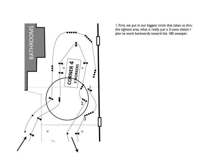
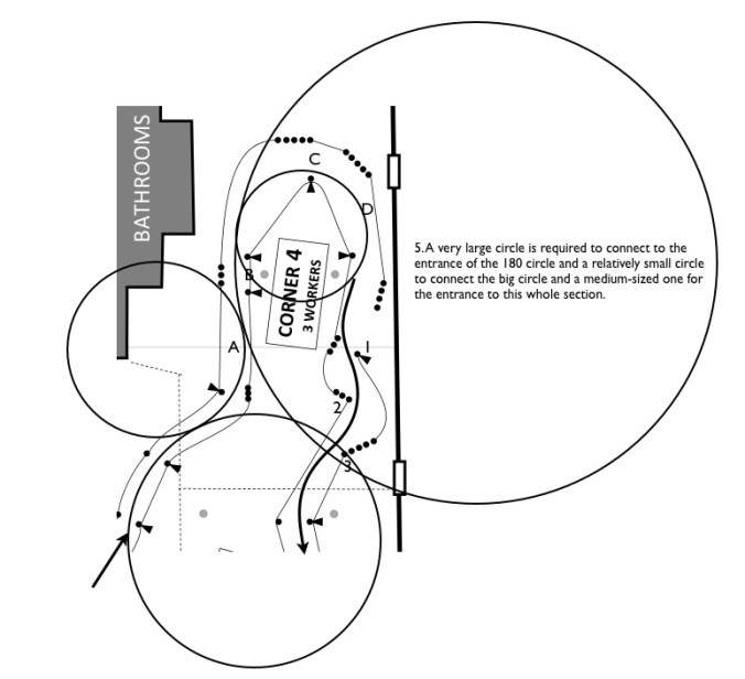
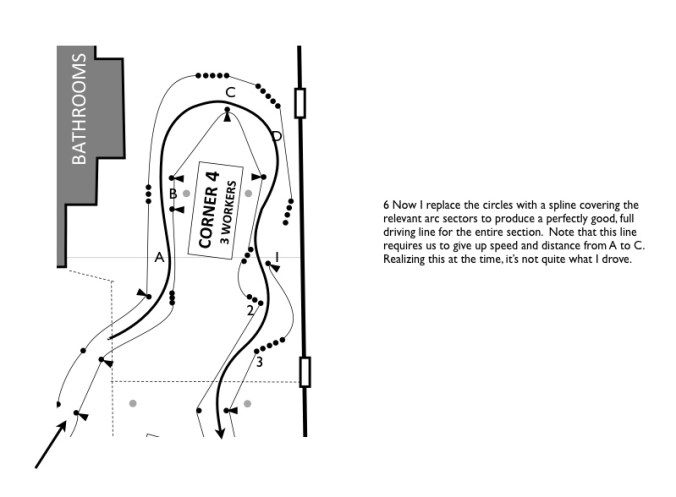
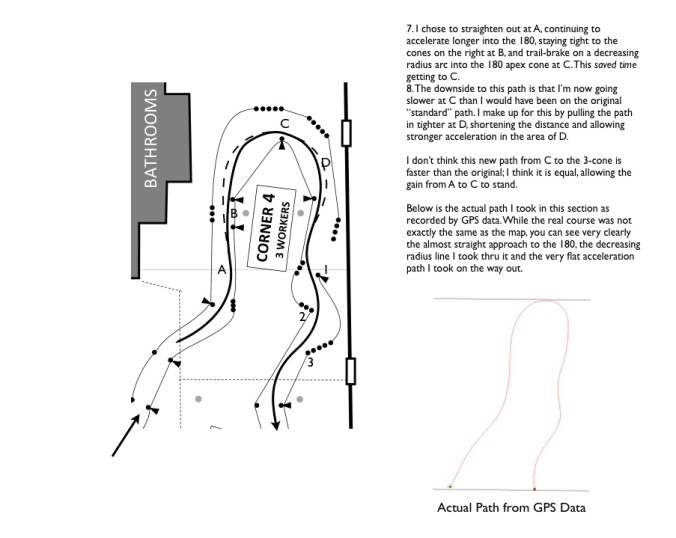
How Much Time Saved?

How significant is a 0.86% increase in cornering power? Let’s put some numbers to it.

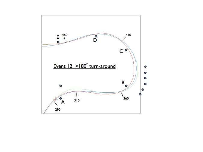
Each year at Dixie Tour there’s a 180 degree turnaround that’s about 160 feet in diameter. At 1g a car can negotiate that curve at 34.61mph. At 1.0086g (0.86% greater) that speed increases to 34.75mph. That extra speed saves 0.02s of time around that turn. Not really very much!

Similarly, if we assume that 25% of a 60s course is spent at max lateral-g, then the time saved over the course is 0.064s. While not nothing, and it could easily be the difference between 1st and 3rd, I’m having my doubts that it’s worth a significant decrease in roll stiffness and the loss of camber that would result.

How Sensitive Is this Result?

Remember that the preceding is predicated on a critical assumption, the 3 to 1 ratio of roll center movement to CG movement. What if it’s only a 2 to 1 ratio, as some have said?

For a 2 to 1 ratio we get a new, final chart, figure 8, below. 

2to1

Figure 8

Notice a pattern? The decrease in cornering power reduction is exactly the same as before, going from 6.7% initially to 5.9% now, the same 0.8% improvement.

The big difference is the decrease in roll. The 2 to 1 ratio of movement creates only a 13.3% increase in roll as compared to 26.7% increase for the 3 to 1 ratio. So, the roll stiffness is very sensitive to how much the roll center actually moves w/r/t the CG height, but the weight transfer is not. These estimates show that I’ve got to have better information. I’ve got to nail down the actual ratio or I’m just spinning my wheels, so to speak.

Also, how do we know that we aren’t decreasing grip faster due to camber loss in roll than we are increasing it with reduced weight transfer? I’ll need to experiment and measure.

How does the roll center actually move? How bad is this extra roll and what does it actually do to transient response.? We’ll explore these questions in Part 2.

More Momentum Maintenance

In my last post I claimed that learning to determine and drive a momentum-maintenance line was one of three basic skills that the beginning autocrosser must acquire in order to Save Time. In this post I’ll give another example, from the same event discussed in the last post, of how I approached a particular section, determined what line I wanted to drive and how I actually drove it as recorded by GPS data.

The course designer was Charles Krampert. Charles posted the course map prior to the event and challenged folks to state how they were going to drive the 180 degree turnaround section. This generated lots of interesting pre-event discussion on the TAC/TVR website (you can see it at http://teamtac.org/e107/e107_plugins/forum/forum_viewtopic.php?104840) with various ideas of how it should be done.

mmm1

Figure 1

mmm2

Figure 2

mmm3

Figure 3

mmm4

Figure 4

mmm5

Figure 5

mmm6

Figure 6

mmm7

Figure 7

mmm8

Figure 8

Beginning Autocross- What’s Important?

944 rake

E-Street 944 I’m Developing

I’ve been thinking lately on what’s most basic and important to Saving Time on the autocross course.

First of all, we have to learn to drive at the limit. Let’s call this Skill #1.

We have to learn to be so sensitive that we can drive right at the maximum capability of the tires and hold it there, or a little below or somewhat above, depending on the need.

Want to be sensitive? You gotta relax. Nothing will impair sensitively like being stiff. Of course, being relaxed while competing is tough. There are some simple signs, like do you have your hands together near the top of the steering wheel? This all but guarantees your shoulders are bunched up, with the bones out of the sockets and you have little sensitivity in your hands. Shoulders need to be relaxed down into the sockets for good connections to the torso to allow the most sensitive control of what happens at the hands.

To hold a car right on the limit, getting every last 1/4 mph out of a sweeper, we’ve got to be sensitive and fast. By fast, I mean we must react fast and early, because a car on the limit is a high-wire balancing act, ready to do something bad (that will slow us down, usually by taking us off our line) at any second. The steering wheel may not move much, but it moves with high-frequency, if relatively small amplitude, motions. As I’ve noted elsewhere, this will produce a smoothly driven car to the outside observer but the driver may feel furiously busy on the inside.

Couple the sensitive, fast hands to steering with the right foot, in order to shift weight forward and back to adjust the line with slight understeer and oversteer and you have basic skill #1 necessary to get the most out of your tires. Right foot steering only works near the limit of tire adhesion. Below the limit the car goes where the tires point. What’s the fun in that?

Skill #1 also includes becoming comfortable with exceeding the tire’s peak capability when needed. For instance, if we need to rotate the car in a corner to exit on the power earlier, then somehow we have to induce the rear tires to take a normally inefficient, excessive slip angle. For a moment. This is why many really good drivers dislike cars that are difficult to rotate. It makes it harder for them to employ a strategy that Saves Time.

Here’s the opposite situation. I rode with a guy this weekend who had an interesting cornering technique. He would take a much too straight and tight line toward a corner, turn late and sharply around the cone, and then mash the throttle. Just past the cone the tires would break loose, the back end would step out, the rear tires would slip with acceleration and then the car would be off toward the next corner. This sort of worked, but he’s still usually last in class.

Why did it work? He runs a late-model, modern sports car with the very capable traction control and stability management on at all times. The car would oversteer a little and the rear tires would spin a little, all under the control of the computer and the car is never going to spin. He had learned to let the computer do about 50% of the turning control and all of the stability and wheel-spin management. I’d never seen anyone use the nannies to such obvious and intentional effect. Do you think he will ever become a fast driver? I don’t either. Not in this lifetime. But, he is relatively safe on a site that has a ditch on one side and poles that can be reached if you are sufficiently crazy/stupid and he’s quite certain his wife would kill him if he damaged the car.

I just tried to get him to open his line up so he didn’t have to brake so much into every turn.

Another aspect of Skill #1: I’ve heard Sam Strano teach a concept called turning at the cones. (No, he doesn’t mean wait ’till we get to the cone to start the turn!) Once I figured out what this meant and was able to do it regularly, I got faster.

I think turning at the cones means, say, when approaching and turning toward an offset gate, we aim the car at the inside cone so that the car’s path, if projected forward and around the arc at that moment, will clearly intersect with and hit the cone.

That sounds kinda stupid, I know. But, here’s the trick: We gotta speed up.

If you speed up then the slip angle of all four tires increases while cornering. The car drifts on a new, larger arc than it would have, an arc that magically passes the car just outside the cone. Without a specific steering input.

In the old days of road racing, when even race tires had huge slip angles, all the corners at race tracks were clearly taken this way. You’ve seen those old movies of races in the 1920’s up through the 1950’s with the car pointing one way but the actual path determined as much by the amount of 4-wheel drift as which way the axis of the car or the front wheels were pointing. We see this a little now in modern-day Drifting competitions, though that type of “drift” used to be more accurately termed a power slide. (They also make it very easy to observe that power sliding from corner to corner, while dramatic, creates a slow way to get around a course.) Modern day Formula 1 cars exhibit slip angles of about 0.0001 degree. They don’t appear to drift at all. This is why mere mortals can’t drive one worth a flip.

I think this drift effect accounts for the common occurrence among the moderately skilled (I include myself in this category) that it requires a slightly out of control run to be fast. It’s easier to carve an arc with a slip angle that is just below or perhaps right up to the most efficient angle for the tire, the angle of maximum lateral G. When you do that you can predict with assurance from the moment of turn-in that you will make the gate. Turning at the cones requires playing on the other side of the peak slip angle. It can be hairy out there. We have to turn-in such that, without a significant amount of 4-wheel drift, we won’t make the gate without hitting the inside cone.

When we say a particular tire is easy to drive, this is what we mean. We can play with the grip on the other side of slip more easily, more controllably. I expect this is why I find the Rival-S easier, and perhaps for me faster, than the RE71R I drove last year, even if it doesn’t produce the better lateral-G number in a skid-pad test.

Skill #2: Driving the momentum-maintenance line

I’ve heard it said that all autocross cars, even super high power-to-weight cars, are momentum cars. I think this is a key insight and mostly true.

I’m not saying there is no difference in driving high-power vs. low-power. If you’re a regular reader you know that I’ve spent a lot of time trying to figure out how different the line should be based upon acceleration capability.

I started autocrossing in a relatively high-power, heavy car (400hp CTS-V) then went to medium weight, relatively high-power car (345hp Corvette) but have now bought a old Porsche 944 with all of 162hp (once upon a time) to drive in E-street. (No, I don’t think it’s the car the have in E-Street.) One of the reasons I did this was because I came to believe that I was never going to master momentum maintenance (in the time available) unless I was forced to by driving a low-power car in a “momentum-maintenance” class. I’m taking advantage of the fact that, for me at least, losing is a great motivator.

To my advantage I have at hand locally one of the greatest masters of momentum-maintenance that ever came down the pike. He headed up Twickenham Automobile Club’s autocross school in Huntspatch last Saturday. I was lucky enough to be invited to attend in the role of an instructor. I think I learned as much as the students I was coaching. I just didn’t get to actually practice the concepts until the autocross the next day.

I don’t pretend to be an expert in the techniques of momentum-maintenance. I’m going to do my best to give you the gist. The school this past weekend showed me how inept at this I am. Give me a couple more years, please. I’m just saying that no matter what class you’re in, you won’t be really fast unless you master the techniques of this skill. Then you can layer other skills, knowledge and techniques on top.

The basic concepts of momentum maintenance, as I understand them, are:

  • Find the simplest, largest radius arcs possible through the tightest, slowest features
  • Work backwards from these largest possible radius arcs to determine the correct approach position so you can drive that large radius arc through the feature
  • Extend these largest possible radius arcs from one feature to the other until they intersect tangentially between the features, usually about half-way in between
  • At the tangent/intersection points turn the steering wheel as fast as possible, within the car’s ability to transition, to produce as much of an instantaneous flip from cornering in one direction to cornering in another direction, just as if you are driving a slalom

Followed with complete rigor, this method of determining the line through a course will produce nothing but arcs, with no straights at all, if the course is tight and busy. Of course, this is not 100% correct 100% of the time, but this is the basic idea. If there’s a long distance between the features then probably the arcs will not intersect. Consider those instances your chance to drive in a straight line, or nearly straight line, remembering that most cars can accelerate fully in 2nd gear and still be turning.

Anywhere the largest possible arcs through the slowest features do not intersect is a distinct advantage to the higher power car or class. Course designers please take note. In fact, it occurs to me that the ratio of total course distance to distance between non-intersecting arcs (or arcs above a certain radius) might be a scientific measure of how much a course favors high-power vs. low-power.

Braking, including trail-braking, and accelerating is generally required only to transition from one radius arc to another, which may include increasing and decreasing radius turns, either explicit in the course design, or implicit in order to connect arcs.

As a real-world example, here’s the starting section of last Sunday’s course, as designed by Charles Krampert:

mm1

First Section of TAC/TVR #4


I felt the most important thing in this first section was to enter the increasing slalom at high speed. The slalom cones were offset the easy way and with increasing spacing so it was full throttle for me end to end, equivalent to a road-race corner leading to a long straight. We will be faster everywhere along that straight the faster we exit the preceding corner. The faster we enter the slalom, the more time is saved.

So, the first thing I do is draw the biggest feasible circle that properly leads into the slalom:

mm2

Big Circle To Allow Fast Entrance To Full-Throttle Slalom

Now we know that if we get onto this circle we can enter the slalom at the fastest possible speed, with the limitation of coming from another corner. If the circle were drawn much larger, no way to get onto it from the previous corner.

Next, we work back to the previous corner and draw another circle, as big as possible that connects to the first circle, but that we know will connect to a circle coming before it and meeting about half-way between. This second circle is necessarily a little smaller than the first one, because of the shorter distance to the previous feature. Just like in a slalom, the shorter the distance between cones the smaller the radius of the arcs and the slower the speed for a given lateral-G capability.

mm3

Second Circle Tangent to First

Here I’ve worked back one more circle:

mm4

Third Circle Reaching About Halfway Between Features


From the start to the third circle there are only two turns, so two more circles. These two are necessarily smaller because the distance between the features is shorter.

mm6

Five Circles Means Five Turns

Now, we draw the momentum-maintenance line, using the tangentially connected sectors of the circles. This is the line I drove and the line that won the class that day. There wasn’t a straight section anywhere. I lined up to start turning immediately from the staging location.

mm7

Five-Arc Momentum Maintenance Line

We normally have to do this circle drawing in our head at the event and “see” the resulting path in front of us while driving.

Now you know everything I think I know about momentum-maintenance. Please don’t get too excited and tell me, well, you haven’t even mentioned looking ahead, you fool! My instructor told me that’s the most important thing in autocross.

Of course your instructor is correct. You can’t properly drive the line I show above without looking ahead and a lot of other things as well. I just can’t put everything in one post. For now, I want to answer the question, “What am I supposed to be looking ahead at?” The answer is not only the cones in front of you, but the path you want to follow through those cones. That path you have to imagine and project onto the pavement.

Which brings up an interesting point. What if someone invented a heads up display that projected the path in front of the car as an assist to the driver. Would it be legal?

Skill #3 is car setup. Even in Street, the lowest preparation class, this is vitally important.

Not many production cars come off the assembly line optimized for autocross. They don’t even have autocross tires as an option! What are the manufacturers thinking? This is annoying, but just the way it is. So, we have to pick up the slack and optimize the car for autocross as God intended.

I’ve never been in anything but the lowest preparation class, so forget about me writing a book on car setup. Not gonna happen. I started this sport late in life. I don’t have time to learn everything.

But, for the raw beginner, I’ll just list the major things that in general need to be done to a Street class car to produce maximum competitiveness.

  • Install wider than stock, top-performing autocross tires. The right brand/model changes over time, but is always a major discussion topic on the internet.
  • Take advantage of the one sway bar change rule. For RWD and AWD, this usually means a much stiffer front bar. FWD cars often do the opposite.
  • Maximize negative camber within the car’s adjustability. Not many production cars allow so much negative camber (approaching 3 degrees) that it will kill your tires in daily driving.
  • Optimize front and rear toe. This is very car specific, but can be done at the site (with a portable jack) and restored closer to stock for the daily drive to prevent rapid tire wear. Test until you know the best settings for your car. I usually adjust one front tire for some total toe-out, then put it back to toe-in after the event by counting flats while turning the tie-rod. Who cares if the steering wheel is a little off-center during the run? (If you do, you can adjust each side equally. But, ain’t nobody got time for that. You should be walking the course, thinking and planning.)
  • Test until you understand the effect of tire pressure and know the range for best grip. This may vary by site surface, ambient temperature, sunlight, etc.
  • Install high-performance adjustable shocks and test until you know what settings work for what level of site grip and bumpiness and how to adjust to conditions on the fly

For most of us, our only opportunity to test is at the events themselves. This is the big bummer of autocross. We must be willing to give up the near (beating someone today) to seek the far (beating many later.)

The higher preparation classes involve exponentially more knowledge and money to be nationally competitive. Of course, you can be fast, have a fast car and have a lot of fun without being totally committed to getting to the pointy end of the spear at any preparation level.


GRM Gets Shock Tuning Wrong

Today, I was reading the latest issue of one of my favorite magazines, Grass Roots Motorsports. In an article about setting up a Mustang with high-dollar shock absorbers I found that what the author says about shock tuning is incorrect.

I don’t mean a little bit off, I mean totally backwards.

Like this: “For example, maybe you want to reduce the rate of dive when trail-braking. You can add some compression at the front of the car, but you can also take some rebound out of the back and accomplish a similar goal.”

What?

Since the rear shocks are extending during braking, the complement to increasing compression resistance in the front shocks is increasing rebound damping force in the rears. You wouldn’t “take some out” you’d add more if you want to slow the rate of dive.

At first, I’m thinking that maybe this was just a simple mistake? The part about reducing the “rate” of dive with added compression was right, if not exactly clear why it might be useful.

Then I got to this statement with regard to cornering: “So, if we speed up weight transfer in the front (by lowering the front compression and rebound settings)…” and my heart sank. I realized that this is not a simple mistake in terms but rather a major misconception about what shocks do on a car.

I suspect the author thinks that by “reducing the rate of dive while trail-braking” he thinks things will happen slower and softer and be more controllable. It seems like he thinks that reducing compression and rebound forces will speed up weight transfer across the axle when cornering, or to the front wheels when braking, presumably on the grounds that this frees the suspension to achieve the final, rolled-over state quicker.  Bzzzzt! 40 lashes!

This misconception absolutely guarantees that you can never figure out how to tune your car’s handling by making shock adjustments.

The truth is just the opposite.

This case illustrates a concept that is difficult to grasp and, I’m here to tell you, difficult to explain. I’ve had this discussion several times with various people and I don’t seem to be able to get it across effectively. (I suspect the shock company representative quoted in the article had the same problem with the author of the article.) I see this as a personal failing. I’m going to try again here, in writing. I suspect it’s hard to understand because it’s a dynamic situation that’s over very quickly and, well, like the author says in the article, people just don’t understand what shocks do. Man, he got that right!

Every time you touch the brakes, move the accelerator in either direction or make even the slightest steering input the shocks do two main things: create forces and absorb energy. Absorbing energy from the oscillation of the springs “damps” the spring (and car) motion and is usually said to be the primary function of the shock (damper).

What shocks do is complex, and we are going to only scratch the surface, but understanding the forces they create is the easy place to start. The textbooks all start with damping. Forget about damping. Forget you ever heard the word. It’s much more important for the autocrosser to understand shock forces first. Focussing on force creation rather than energy absorption is the key insight that I hope will allow me to get my main point across.

So, what do shocks do? They produce forces that always resist motion. They resist pitch, roll and twist of the car. In so doing, they speed up weight transfer and slow down the motion they resist.

This speed-up-weight-transfer/slow-down-the-motion concept strikes many as paradoxical and may be why it gets misunderstood. But, really, it’s not very complicated. If a mass is set in motion and you create a force opposing that motion, then you will slow down that motion. It will, therefore, take longer for that motion to complete.

Let’s start by imagining we have a car with springs but no shocks.

Now, apply the brakes.

The dive downward in the front that results is resisted by increasing force in the front springs as they compress. (The opposite happens at the rear.) Where does the force go? It goes into the tires. They do the braking, not the springs, right? So, that’s where the forward dive load (forward weight shift) ends up. It goes into the tire contact patches and, as we all know, this increases the braking capability from the front end of the car while reducing it at the rear.  Remember, the additional compressive loads in the springs are “reacted” immediately by the road at the contact patches. There’s no other place for it to go. Newton’s third law, etc.

With just the springs it would take some finite time, let’s say 2 seconds, for the sake of argument, for the extra load to build up on the tire patches. (I say “extra’ load because the front tires always had their share of the weight of the car on them to begin with.) It builds up linearly with spring compression distance because the springs are generally linear in their action. That’s why one number, the spring rate, can usually describe how they work. A 200lb increase in force for each inch of compression, for instance, might be the spring rate for each front spring on a stock car. If there are no shocks this is exactly the same thing as saying the weight transfer isn’t complete until the dive motion ends. And you won’t achieve full braking at the front (full load at the contact patches) until the forward dive has reached it’s final position.

This sounds suspiciously like what the author of the GRM article was thinking. Remember, this is with no shocks on the car.

How much weight transfer occurs? If we assume our 200lb/in spring compresses 3 inches in those 2 seconds, then we’ve got 3in x 200lbs/in = 600lbs of weight transfer to each wheel, or 1200lbs total that wasn’t there before. That 1200lbs has been transferred off the rear wheels, of course, which is why rear brakes are smaller in size and heat capacity than front brakes on most cars.

Now, reinstall the shocks and brake again.

The front shocks will develop a compression (bump) force more or less proportional to the rate at which the shock shaft moves (the shock shaft velocity) as the dive begins. This force resists the compression of the shock. These forces can be very high if we want them to be. For instance, a shock could develop 400lbs at 1 inch per second of shaft speed. (Ok, so it’s a little on the high side of normal practice. Please bear with me.) So, now, when the springs might have compressed 1 inch and the shock shaft is moving 1 inch per second we have 200lbs of new force from the spring and another 400lbs of new force created by the shock.  Again, all such force is reacted by the road at the contact patches of the tires. The shock has barely moved, the dive has just begun and we already have our full 600lbs of weight transfer to each front wheel. All that extra weight that the front tires “feel” came off the rear tires and it got transferred in approximately one-third the time (only 1 inch of motion out of 3 inches total that will eventually occur) as without the shock in place. This is the essence of “increasing the rate of weight transfer.”

The resistance to compressive motion provided by the shocks adds to the resistance from the springs and it happens as soon as the shaft starts moving. It starts to happen early, long before the springs have reached their final, compressed state. Just like the spring resistance created a load increase (weight transfer) into the front contact patches, the shock resistance does the same thing.

Imagine that the front shock has so much resistance to compressive motion that it would only let the shaft move at, say, 1 inch per hour, even if you pushed on it with a million pounds of force. In that case, weight transfer will be essentially instantaneous without hardly any dive motion ever taking place. Hit the brake and the loads at the tire patches instantly increase due to weight shift. A little bit of the load increase (weight shift) comes from the springs, a whole lot comes from the shocks. And essentially no dive rotation has taken place! We need to get this point: thanks to the shocks, weight shift need not be directly proportional to body rotation, either in pitch or roll or combined pitch and roll (twist).

The super-stiff shocks in the thought experiment have now created a kart. You can’t get weight transfer faster than with a solid, non-movable suspension like on a kart. You don’t doubt that weight transfer occurs in karts, do you?

Given this scenario, the car never gets to full compression of the front springs. Not in any reasonable amount of time. But, full weight transfer was achieved (except for the extra that would have happened due to the suspension motion, which is mostly bad anyway, especially when cornering) and it happened fast, long before the springs were ever fully compressed.

Shocks make more of the weight transfer happen earlier by creating forces that resist the shaft motion. They front-load the weight transfer. At the same time, they reduce the rate of pitch or roll, making the car take longer to achieve the final, stable position, on which the shocks have no effect, neglecting the effect of pressure in gas-pressurized shocks.

Do we care how long it takes to achieve the final position? Not much. We got our braking force earlier in the braking process than otherwise. We didn’t have to wait those agonizing 2 seconds for the full dive to occur. That means we stop in a shorter distance.

Yep. Shocks can have a big effect on real-world stopping distances, even though the tires and the brakes haven’t changed. Worn shocks can kill you on the street, not only with poor handling but with increased braking distances.

The same thing happens when cornering. The compression damping from the outside shocks and the rebound damping on the inside shocks both create forces that resist roll, slowing it down, and, by doing so, increase the rate of weight transfer across the axles because all forces created are reacted only at, and immediately by, the road at the tire contact patches.

So, one way to tune the car with the shocks is to set how fast we load up the tire patches and to control which ones load up earlier or later than others in the differing conditions of pitch and roll the car encounters. Loading up the contact patches too fast makes the car hard to drive and easy to lose traction due to loss of compliance. You may be forced to slow your hands when cornering for instance, to keep from impacting the tire contact patch so hard and fast that it loses traction.

Too slow is terrible, at least in autocross where transient response is so important. A big difference in load rate front to rear will create an unbalanced car because one end will load up and reach the limit faster than the other end. When that happens, that end of the car starts to slide.

If a car is naturally unbalanced due to other factors, then we may be able to re-balance it with shock tuning.

To sum up, slowing the rate of pitch or roll is achieved by resisting it. To do this we design the shock to create a force that resists the motion of the shock shaft. Resisting shock shaft motion increases the rate of contact patch load change because the resisting force is created immediately with any shaft motion and very quickly reacted (through the structure of the suspension, wheel and tire) by the road at the contact patch. You might say the force is “created” in the shock, “travels” to the tire contact patch and is “resisted” by the road.

Here’a real-world example of the forces developed by shocks intended for street-class autocross where the springs cannot be changed. These are the force curves for the shocks I’ve been running on my Corvette. The positive curves are for compression and the negative curves are for extension (rebound). At only 1 inch per second of shaft velocity each front shock produces about 220 lbs of force resisting the compressive direction with the adjuster 5 clicks down from the maximum. The rears are a little less. At the maximum adjustment the force values are even higher.

Above 8 inches per second the forces are over 400 lbs in both the compression (bump) and extension (rebound) directions.

shockdyno1

2022 Addendum: The shock forces shown in the graph above turned out to be too high, especially front compression (at all velocities) and both front and rear rebound at high velocities. After I learned to figure out how much force the shock “should” have I ran them at much reduced settings and received increased grip, but there was not much I could do about the linear rebound curves less paying up for specially-valved double-digressive pistons.