This post presents a real-world data example of a 2-Cone Turnaround from the Bristol Fall Champ Tour just last weekend. Same car, two different drivers.
Figure 1 shows the GPS path plots of two different runs, Red and Blue. I’ve added the approximate location of the last cone in the preceeding feature at “A” and the entry and exit cones that define the turnaround. I’ve also annotated the paths with some other information from my 20Hz GPS data device that may be interesting.
Figure 1
Similarities: Both cars pass point “A” at an identical speed of 55.0mph. Both cars were very close to the entry cone as verified by video and both drivers downshifted to 1st gear without difficulty or incident. The minimum speeds for both cars are very similar, as are the peak lateral G figures recorded by the data device. Both cars trail-braked effectively right into the geometric center of the corner though Red’s data shows a slightly more “perfect” brake release than Blue. Blue’s path appears more circular and Red’s path closer to a spiral as a result. Both cars began to smoothly add throttle at almost exactly the same location which was near the “23.8mph” arrow. Both cars reach their maximum lateral G figure at almost the same location around the turn at which location a slight slope began that assisted turning. (Otherwise the G-peaks would have been closer to the minimum speed locations near the center.) Finally, at point B both cars reached exactly the same speed of 48.5mph. Frankly, I’ve never seen two sets of data by co-drivers look so similar in so many respects.
Differences: The key difference is that Blue enters and exits the turn with essentially zero angle on either the entry cone or the exit cone. Red has made sure to obtain at least some angle on entry, about 7 degrees as close as I can measure. (This cost Red an initial loss of 0.03s which was quickly made up.) Red also doesn’t try to be perpendicular to the line between entry and exit cones when he passes the exit cone… he allows an exit angle. This allows some of the turn to be completed after the exit cone where turning while simultaneously accelerating fully in 1st gear was still possible. (Gotta love those Yokohamas!) Of course the effect of the 7 degree entry angle is the tighter line achieved by Red all around the turn. Neither driver even considered trying to add width to the entry. There simply wasn’t sufficient time or space to do so. Neither driver tried to add width to the exit. The geometry of the next feature favored exiting right on the cone, though Blue slightly missed it, as shown in the GPS path trace and as also confirmed by video.
Result: The tighter line achieved by Red resulted in 24′ less traveled and a stunning 0.38s time saved over the distance from A to B, almost all of which was gained in between the entry and exit cones.
I think this is a good example of how constrained we are so much of the time in autocross. The approach speed and pinched entry and exit geometries made it impossible to add width to either the entry or the exit of the turnaround without paying a severe price. In effect, the usual advice to “use all of the track” had no applicability in this case, which I suspect is quite common in autocross. On the other hand, making the effort to achieve a relatively small angle on the entry cone and allowing an angle to remain at the exit paid great dividends.
Note: Post was updated 9/11 to include distance traveled information.
Part 2 will be mostly concerned with 2-cone turnarounds. We will explore the complications of entry and exit widths and angles. From this we’ll also get some insight into asymmetric 3-cone turnarounds where cone 2 is not in the center.
Let’s start by drawing one of the 2-cone turnarounds at the Bristol Champ Tour earlier this year. It was about 80′ across from cone 1 to cone 3 and had entry and exit gates in the range of 20′ wide. I’m going to ignore the fact that the whole feature had a significant slope downward from cone 1 toward cone 3 but in the real event, of course, it played a significant role. (Effectively, the car turns better in the first half of the turn and worse in the 2nd half. This make a symmetrical turnaround (as seen from above) asymmetrical when driven.) This turnaround is represented in Figure 1.
Figure 1
I’ve added a green rectangle to represent the width (75”) and wheelbase (107”) of a typical car, something close to a Mustang GT350, in fact. I think we need to do this to be more realistic than in Part 1 because the size of the car becomes meaningfully large and limiting compared to the turnaround geometry once we start thinking about where to place the car within the gate width and what angle to set. I will use the left side tires as the definition of the line, not the center of the car, since we’re turning left and need to pass the cones on the left side of the car.
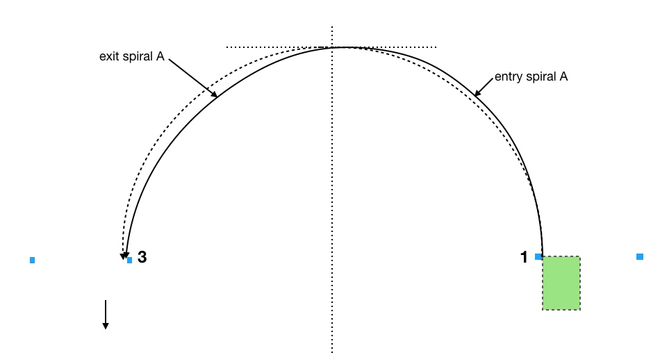
Figure 1 shows a 40’ radius dashed reference arc. An extremely low-powered car plus a requirement for a perpendicular exit will result in driving something like this arc in a generic turnaround. However, autocross corners are usually so tight and slow (as compared to most race tracks) that even “low-power” cars can use a slightly spiral exit, something like exit spiral A. The spiral entry shown, entry spiral A, assumes we enter perpendicular to the gate like we did in Part 1. Now we are going to change that assumption.
In Figure 2 we add an angled entry leading to entry spiral B.
Figure 2
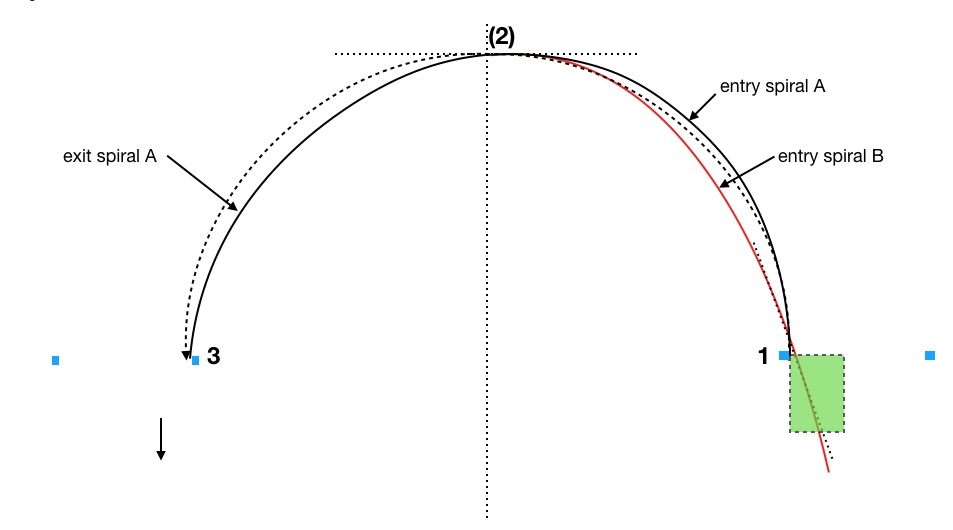
Does entering at an angle help reduce our time? Let’s look at Entry spiral B, the red path in Figure 2, which enters at a 20 degree angle at cone 1.
We can state 2 things about this path: 1) from cone 1 to the former location of cone 2 (that we removed) the path is shorter, and 2) the total amount of turning necessary from cone 1 to missing cone 2 is only 70 degrees instead of 90 degrees. If entry spiral B can connect with the exit spiral A at the same speed as entry spiral A then I think it’s obvious that entry spiral B takes less time. It’s shorter, the car has to turn 20 degrees less and it can arrive at the previous location of cone 2 at a higher speed. In fact, if we don’t modify our speed we will be too fast at the former location of cone 2 to transition to exit spiral A.
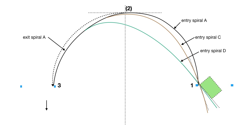
So, we need a new apex point to take best advantage of the entry angle, something like what’s shown in Figure 3 as entry spiral C.
Figure 3
This ties in with another thing Brolliard teaches us, namely that we want to take advantage of as much of a 90 degree entry spiral as possible for any corner of 90 degrees or more, which in Figure 2 we did not do. Now in figure 3 we have a full 90 degree entry spiral and the apex, denoted by a phantom brown cone, becomes displaced beyond the centerline where we have no problem transitioning to exit spiral A.
This is what should happen, I believe, when you can create an angle on entry but can have no angle (or less angle) on the exit: the apex point moves toward the exit.
Can we improve with even more entry angle? Look at Figure 4.
Figure 4
Entry spiral D enters at 40 degrees and connects with exit spiral A at yet an even later apex. It is clearly shorter and straighter to the center line and the entire path from entry to exit is clearly shorter. It also passes the entry gate at an even higher speed than entry spiral C so its average speed from the entry gate to the apex is higher. Finally, it turns less from entry gate to exit gate, exactly 40 degrees less, but, again, we do turn 90 degrees from entry to the new apex where the entry spiral joins the exit spiral.
Of course, there’s no free lunch, or not very often, anyway. We always have to weigh the cost it took to achieve that 40 degree entry angle at high speed which transformed the nominally 180 degree turnaround into only 140 degrees. If getting the entry angle is free, or nearly free, then use as much angle as you can get and fit a 90 degree entry spiral into the feature. Usually we have excess speed on approach so we can do this. (Without excess speed our exit would end up inside cone 3 if we kept the tires working at the limit. In that case the feature is no longer a single corner. It becomes an acceleration zone (or a “curved straight” some people call it) and only later a corner.
When thinking these things through remember that Brouillard has taught us that what counts is finding the path that gets us to the exit gate first. The point is Saving Time, as someone(?) once said. Even if we are only going 5mph at the exit gate, when a different path (go out wide to the next county?) could have us arrive at the exit gate at 150 mph, the car that went deep never catches up no matter how far it is to the next feature even assuming the car can accelerate above 150mph at the same rate from that point onward. We can always find a (stupid) way to start our acceleration at a further location back from the exit. What counts is starting our acceleration at an earlier point in time. As I’ve said before, it rarely pays to go in the wrong direction no matter how fast you travel. Taking a bigger arc (longer path) or less angle in order to increase velocity is “going in the wrong direction.”
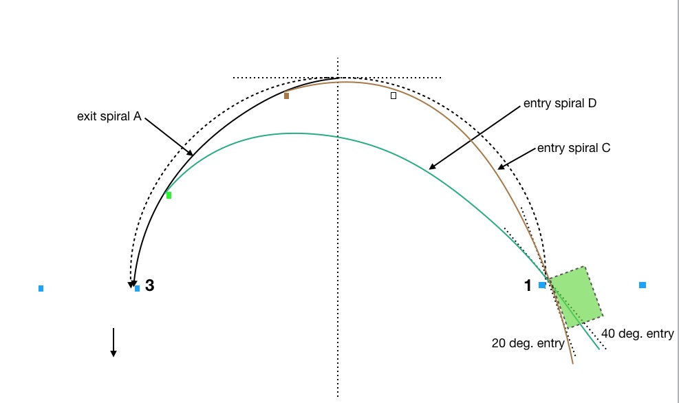
It seems that we have discovered something about 3-cone turnarounds that have offset apex cones. Take a look at Figure 5.
Figure 5
Entry spiral C is equivalent to having the brown cone placed for real at the apex. This 3-cone situation occurs often in autocross, i.e. we have 3-cones but the center cone is offset one way or the other from the center. It may also be deeper than it’s nominal position on the point of an equilateral triangle as I assumed in the previous figure. This tells us that for offset apex cones we want to enter at more of an angle the more the cone is offset closer to the exit, up to some point where we begin compromising the exit. This allows the use of a full 90 degree entry spiral. If we can’t enter at the best angle, or if getting that angle requires too much of an earlier compromise, then the best we can do is to perform a 90 degree entry spiral, even up to a straight-in entry, with an earlier apex out in space. Our exit spiral must then pass by the brown cone.
What if we have a cone offset toward the entry as shown by the empty box in addition to the brown box? Then, still using entry spiral C, we simply pass by it on the way to our most efficient apex at the brown cone. In fact, any cones that happen to lie just inside our most efficient entry spiral based upon entry angle are simply passed by on the way to the best apex. Turnarounds often have cones thrown out there that may or may not be apex cones and may not act as line constraints either.
Don’t we want to enter and exit as wide as possible (using all the available track) at as much angle as possible? This makes our turnaround significantly less than 180 degrees, which should mean it can be done faster.
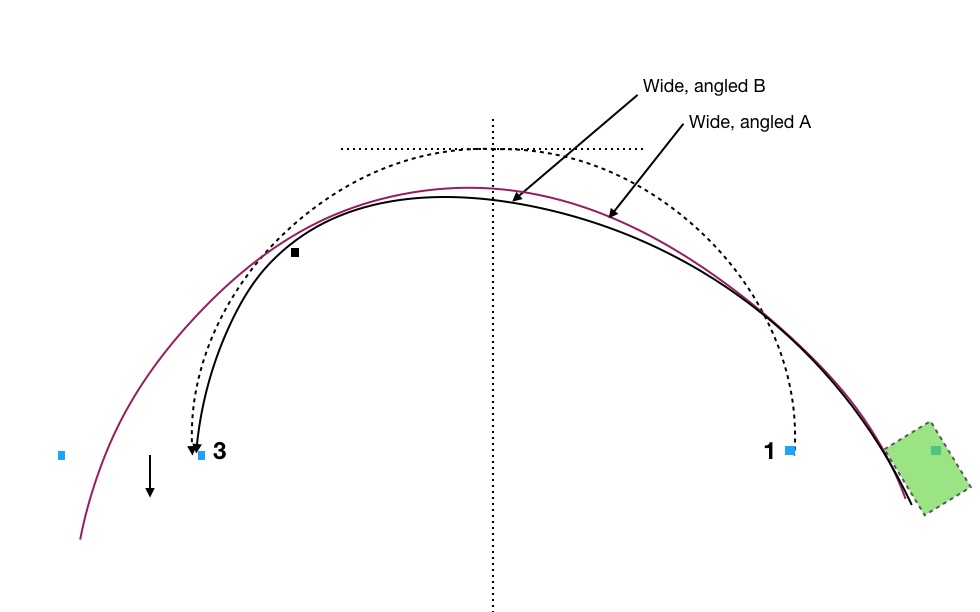
The answer is Yes, but with reservations. We can minimize our time in the corner this way, the time from entry gate to exit gate, with path wide, angled A, as shown in Figure 6, for instance. If we have an offset 3-cone situation (the black square) and a need to have a perpendicular exit we use wide, angled B, which will be slower than path A. More braking will be required prior to the apex at the black square in order to produce an exit spiral that achieves the perpendicularity requirement at cone 3.
Figure 6
These wide and angled entry and exit paths work if 1) we have lots of speed to use at the entry, 2) it doesn’t cost us much to get the angle and position and 3) an angled exit works for the next feature. But note the issue with the car. We have become severely limited in how wide we can enter due to the size of the car as compared to a typical entry gate which is a minimum of 15’ but usually about 20’ as drawn. This often constrains the possible entry and exit angles and widths such that the ones I’ve drawn in Figure 6 are untenable.
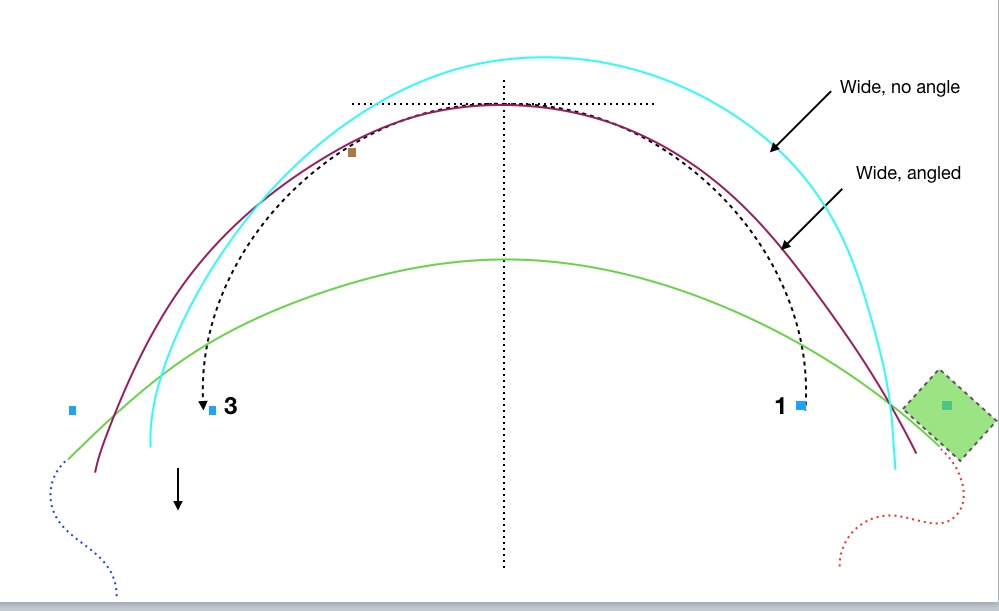
This brings up an interesting point. Why wouldn’t we always take the widest and shallowest possible arc through the entry and exit gates if there is no apex cone? Why would we ever take Wide, angled in Figure 7 which goes so deep and apexes at the brown cone (whether it’s there or not) after turning 90 degrees, if we could take the extremely shallow green path in which we don’t even turn 90 degrees?
Figure 7
The answer is that we do want to take a shallower path, all else equal. If we can fit a larger radius path in between gates 1 and 3 then we want to do that. Don’t turn more than you have to, as long as its consistent with using high-efficiency entry and exit spirals, doesn’t involve a big cost to get to the entry and still correctly sets the car up for the following feature. I hope it’s obvious that you would never want to take the red dotted path, for instance, just to connect with a wide entry and shallow, low turning path. Nor would you want to take the green path only to have to do something crazy like the blue dotted path to set up for the next feature.
The 2-cone path that we really want to avoid would be a wide entry with no angle. This is analogous to the mistake of substituting a faster, larger circle for a smaller slower circle. Every degree of angle we can achieve at low cost significantly decreases path length and time in the turnaround. I’ll publish a real-world example in the next post.
I think if you have the gate width and an entry angle that works, then use them, as long as they don’t cost too much to obtain. Unfortunately, all too often the cost is too high and we have to compromise.
I recently chased cones in the turnaround on the left course at the Great Lakes (Peru, IN) Pro-Solo in June of this year. I thought some drivers went too deep, either by design or braking too late or having no angle on the entry. I thought a few actually went too shallow via an extreme entry angle and paid the price on the exit where they needed to be almost perpendicular to the exit gate.
It got me wondering how much I really understood about turnarounds.
Then at the Bristol Championship Tour a few weeks later the course contained two 2-cone turnarounds, both complicated by a sloping surface. Since then I’ve been thinking about turnarounds even harder and started drafting this blog post.
This past weekend I went back to Bristol, for the Fall Championship Tour event, and, sure enough, they had two more 2-cone turnarounds. I got to use some of what I’ve been developing for this post.
Autocross line theory is complicated. More complicated than line theory for race tracks. While the physics is the same, autocross course designers, sometimes by accident, sometimes by design, do crazy stuff that would never be tolerated at a race track. In addition, while race track turnarounds have various inside edge geometries, none have no inside edge at all as is usually the case with autocross turnarounds. In this series of posts (there will be at least two) I try to make sense of the wide variety of turnaround types we find in autocross.
Starting Common and Simple
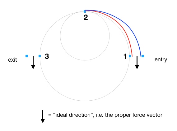
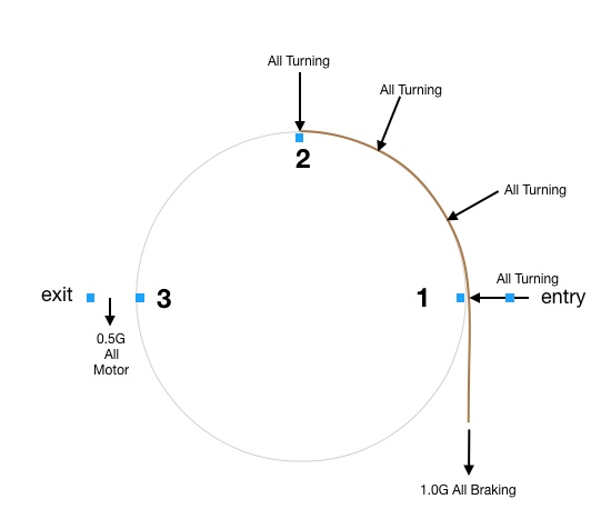
Let’s start with the most common “3-cone” 180-degree turnaround as shown in Figure 1. For simplicity, we make the key cones lie on a circle with cone 2 in the geometric center. I’ve drawn a gate at entry and exit.
We shall assume that the “ideal directions” as defined by Brouillard in The Perfect Corner (available here) and illustrated with arrows are vertically downward as shown. These are the directions in which we must maximize the car’s acceleration on either side of the apex cone. In a 180-degree turnaround where we neglect entry and exit complications the direction is directly back from where we came on both entry and exit. (When you brake a car you are accelerating in the backward direction.) For the moment I won’t bother to show an exit path.
Figure 1
In The Perfect Corner Brouillard teaches us to a) fit the largest possible Euler spiral that reaches 90 degrees at the apex (cone 2) in order to create the highest possible minimum speed at the apex, and b) use “all the track” which, in the autocross case, I’m going to say means to use the blue path instead of the red path. Please forgive the precise shape of the paths. They’re “representative” of spirals, but are not precisely correct.
I understand that we may not have as free a choice about this in autocross as you might at a typical race track. For now, in order to get some basic understanding, let’s assume we could take either path freely without paying a penalty.
Points to understand:
The red path turns 90 degrees in a shorter width and therefore a shorter overall length, so the radius changes faster. Since the radius determines the car’s maximum speed at any point (we are always 100% on the limit, right?) then a car on the red path has traveled at a lower average speed than a car on the blue path.
Since the red path turns 90 degrees within a shorter distance the car must start the turn at a lower speed than blue, i.e. it must brake more before turning in. So, if both cars approach the feature at the same speed, the car on the red path must brake more and enter a smaller, later spiral than a car on the blue path.
The car on the red path is traveling slower at cone 2 than the car on the blue path. It’s not evident from the picture, but the red radius must be smaller than the blue radius at cone 2. I drew another smaller circle to illustrate and make clear that all cars at point 2 do not have to be on the same radius.
But, but, but!!! I hear you saying, the red path is shorter! And we all know (don’t we?) that travel on a smaller radius circle Saves Time compared to traveling on a larger radius.
Yes, it does, if you travel on a constant radius and just go in circles, but that’s not quite what we are doing here. We haven’t yet even talked about the primary reason the blue path, even though longer, takes less time.
To really understand why the blue path is faster, though longer, we need a little more physics. In effect we are asking why the rule has always been to use the entire track width at corners on a race track. If distance was all we had to worry about then there would be cases where we just brake down to almost zero speed, make the turn at as close to zero radius as possible and then accelerate away. In the 1970’s investigations using hand-held stopwatches proved that that was not the fastest way around a pin cone for a typical autocross car. They may not have understood the physics but the stopwatch proved it.
The real answer to why we use the entire track width is that it makes better use of a key fact about most, but not all, cars. This means that the blue path is not necessarily faster for all cars, just the ones we autocrossers usually drive.
This key fact is that most cars are significantly limited in forward acceleration as compared to braking and lateral acceleration. Even for a high-powered car like an A-Street Corvette (the most popular at this time being the sixth-generation Z06 model or C6Z06 for short), the peak forward acceleration at autocross speeds in 2nd gear is only slightly more than 0.6G. The peak lateral acceleration is much, much higher at over 1.2G and braking is somewhere right around 1.0G, according to all the data I’ve seen.
This means that such a car can theoretically “turn around” faster by turning rather than by braking and reversing in a straight line, even if it could reverse as fast as it could go forward.
This is also why F1 cars drive lines very similar to E-Street Miatas: in spite of their massive power they have even more lateral acceleration capability thanks to aerodynamic downforce. It’s the ratios between these factors that determines the most efficient cornering line. The proper line is different for every car type. Some differ by a little, some by a lot. So, there’s no such thing as an absolute proper line for any particular corner. It depends on the car.
The ratio between lateral and longitudinal accelerations is also why high-powered 4WD Rally cars don’t necessarily use all the track. They turn smaller radius, Scandinavian-flick assisted turns because they have as much or more longitudinal acceleration on dirt as they have lateral acceleration, thanks to high-power 4WD and tires designed to lock into the loose surface. They need to get pointed in the new ideal direction as fast as possible to best use that longitudinal acceleration capability. F1 cars and E-Street Miatas and A-Street Corvettes with grippy tires on grippy pavement do not. I think many people have been confused on this point.
Therefore, if you autocross a powerful and very light 4WD car on drag radials you may very well be correct in taking a significantly differently line than your 2WD competitors!
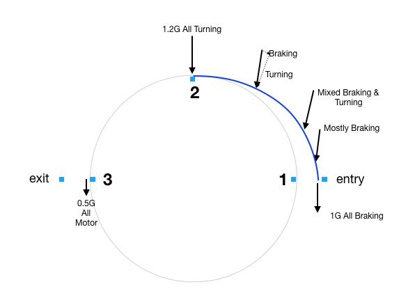
To help illustrate all this, I’ve drawn Figure 2 with arrows to indicate the vector sum of the braking and lateral accelerations at various points along the blue spiral path.
Figure 2
The braking component is always pointed directly behind the car and the lateral component is always pointed sideways to the car. Add them together nose to tail and you get the resultant, shown as solid arrows.
All along the path the arrows mostly point in the ideal direction. Initially it’s all braking, which uses all four tires (but not equally, due to weight shift) to produce an acceleration vector of about 1G pointed back the way the car enters the corner. Then, as we trail off the brakes and turn the car more the lateral acceleration begins to dominate. Again, like braking, this uses all four tires, but, again, not equally due to weight shift. At cone 2 we have the full lateral capability of 1.2G pointing directly parallel to the ideal exit vector. This ever-changing trade-off between longitudinal and lateral acceleration during the corner is what makes the path take a non-circular, spiral shape. Theoretically, the car reaches peak lateral G only at the apex when the brakes have been completely released and the car is at the cornering limit.
Think about this: at the apex (cone 2) the car is being pushed in the proper, ideal direction at 1.2G. This value is nearly twice what the engine in our C6Z06 can do at the exit! And most of that push will continue beyond the apex as it’s only gradually replaced by the engine acceleration. The fact that the car is, at the apex, headed for the edge of the “track” doesn’t matter. (Unless you run out of track!) At the apex the car is being pushed in the new “ideal direction” with the greatest force, and therefore the greatest acceleration, that it will see anywhere in the whole process of turning around. This is why we want to get into this state and stay in it as long as possible. This is the physical reason for “use all the available track.” We wish to use the high lateral acceleration capability of the car to get turned around in the least time.
By contrast, if we drive a circular path, created by first straight-line braking and then, as instantaneously as possible, turning in at the limit all the way to the apex, we get the (slightly simplified) situation in Figure 3.
Figure 3
Initially it’s all braking and we must brake more than the spiral path, but at least the vector points in the correct direction. It’s a slightly smaller vector than the all turning vector, being somewhat less than 1G in our C6Z06. But after that point we get larger, all-turning vectors all the way to the apex. At the apex things are great, but for the first half of the turn the vector arrows point toward the center of the circle, which is mostly a waste of tire capability. We don’t need so much force to get us over to the apex. We only need a little to get us over there. Not much of the vector force is accelerating the car in the ideal direction, which is back where we came from. This is why a circular entry is not as fast as a spiral entry. It doesn’t use the high lateral forces the tire is capable of generating very efficiently. A circular entry does not use the “multi-tasking” capability of the tire, i.e. the ability of the tire to brake and turn simultaneously at a higher combined value than either task alone. In the last few years ultimate performance street tires have greatly improved at multitasking, making spiral entries and exits even more important in street tire classes than previously.
The Thought Experiment Proof
Ah, but Ed, you still haven’t convinced me that a wide spiral path (blue) is faster than a narrow spiral path (red), I hear you say. OK, you’re right. Let’s draw some various spiral paths and see what we can learn.
This is where I’d usually introduce a bunch of data. Sorry, but I don’t have it. Lots of other people have taken it, however, so I don’t feel I need to prove that using all the available track is correct. I’m just trying to explain why (and when) it’s correct.
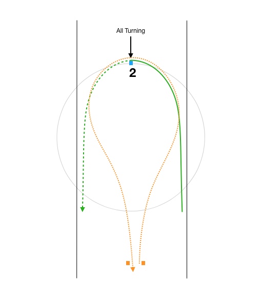
What I can do is add red, green and orange paths of ever tighter and smaller spirals as in Figure 4 and see what happens.
Figure 4
I’ve started all three paths with a solid line at the approximate point where the spiral (the actual turning) starts. For the blue path the turn begins at the horizontal baseline. All the others can’t start turning until later. Can you see why? If they started turning earlier they wouldn’t make Cone 2. They would pass underneath it.
While the green and orange paths don’t pass inside either the entry or exit gate they make it easier to see what happens as we pursue tighter and tighter turns. A car on the green or orange paths could, of course, take either the red or blue exit path, but there’s a problem with that we’ll discuss in a moment.
Let’s assume that the blue path will require no braking prior to it’s start, that is, we arrive at the baseline at exactly the correct speed for the blue entry spiral. For all the other paths we arrive at the baseline at exactly this same speed.
Since the red path turns faster (has a smaller radius) than the blue path we will have to brake down to a slower speed to enter the spiral portion. Let’s assume that this braking point is at the red dot on the baseline. I think you can imagine that something like this is the case. The green and orange paths are even tighter, so we must brake down even more before starting the turn. At least all the straight-line braking beyond the baseline has its vectors pointed in the correct direction.
The key point of the proof is this: as the entry spirals get tighter the speeds near cone 2 approach zero. That means that the time necessary to travel a tighter and tighter path (at near-zero speed) approaches infinitely long. We can safely conclude that each smaller spiral path as we descend from blue to red to green to orange takes longer. Yes, the distance is getting shorter, but not by much. The shortest it can get is the straight line distance from the horizontal baseline drawn through the colored dots to cone 2. The distance never approaches zero. In fact, the tighter you try to take it at cone 2 the less the distance changes. At the same time the smaller radius is rapidly forcing the car to approach zero speed at the apex.
What about the exit? Let’s say that at cone 2 the car on the blue path is traveling 40mph. The car on the orange path can’t be going nearly as fast. Let’s say it’s going 5mph. It’s still at the lateral acceleration limit. We can always find an orange path radius where that’s at only 5mph. How long will it take for the car to get back to the horizontal baseline if it’s only going 5mph at Cone 2? A long time, that’s how long.
Now, once rotated around cone 2 on a very tight orange-path radius our C6Z06 will accelerate back out at 0.6G. The same car on the blue path begins its acceleration from cone 2 toward the horizontal start line at 1.2G and gradually drops down to 0.6G as turning ends, so the average is somewhere between 1.2G and 0.6G, which is necessarily much higher than 0.6G. Therefore, a car on the blue path will exit in less time even though it must also traverse sideways to the exit. Traversing sideways to the exit is essentially free, plus we have to get out there anyway! Here is the key point which may not be at all obvious to those who don’t have a PhD in physics: all that counts in calculating the time to get from cone 2 back out to the horizontal baseline is the average magnitude of the force vector in the ideal direction. The blue path is a faster exit because it makes better use of the 1.2G lateral acceleration capability of the tires for a longer duration after the apex.
We should notice something else interesting happening with the gradually tighter paths. While any of them could connect to the blue exit path, the car will be moving too slowly to use it efficiently. This is because a car on any path inside of the blue path has to negotiate a tighter radius to get there. That means the car must be traveling slower at cone 2. The driver would have to open the wheel and add throttle as she approached cone 2 in order to make best use of the wider exit and get out to the exit gate. Of course, we’ve all done exactly this when we realize we’re too slow and tight as we approach an apex. So, that’s exactly what we do. We open the wheel and add power to get back to the limits of the tires. But, we all recognize that it was a mistake to get into that situation.
If the entry and exit gates are such that you’re forced to follow the green path by the turn geometry, as we sometimes are, well, so be it. It’s the best you can do. But, if the course designer uses cones to force every car to take the same narrow path, say the green path, then the car with the bigger power to weight ratio (or 4WD) wins every time. This is the difference between a standard corner and a “dig.”
The 1-Cone Turnaround
This is a good place to introduce our first autocross special case, the airport runway pin cone or what I call a 1-cone turnaround as shown in Figure 5.
Figure 5
Imagine we have a narrow airport runway with a single cone designating the turnaround. Now the narrow green path in Figure 4 starts to make sense. You will approach as fast as possible, brake as late as possible and spiral in by trail-braking… to the limit of the car’s capability, and start adding gas at the cone. Pretty simple. Any other path will take more time.
If you want to take a smaller radius path and slide the back end of the car around thinking that the “rotation” will make you faster because it gets the car pointed in the new direction earlier so you can get on the gas earlier and you are not driving a powerful 4WD World Rally car on tarmac tires then please go ahead and get really good at that. Tell all your friends how fast it is. (I need all the advantages I can get.)
Sometimes these wacko course designers even put a single gate through which we must both enter and exit, like what’s shown in orange. Sheesh! So much trouble! Now we have to create a false chicane to get out to the proper line and back after the turnaround, but I think most of the time you drive the corner the same, otherwise. Use all the available width.
Yes, you can certainly create a geometry where the extra distance getting out wide makes it slower. The closer the gate is to the cone the more the false chicanes’ extra distance hurts. In that case you need to balance the factors. You might actually want to use tighter entry and exit spirals if you must pay too much to get out to the edge.
In the special case of the narrow runway pin cone the specific size of the Euler spiral you take is generally dictated by the actual width available. You get to choose your entry speed which will be dictated by the specifics of your car. This is why we must practice trail braking in various situations from various speeds to get a feel for what works the tires the hardest and gets you around the corner the fastest.
In the next post I’ll explore the 2-cone turnaround and the interesting subject of entry and exit angles.