Basics Of Shock Absorber Tuning- 2

From time to time people ask me things like: “Why do you give away all this stuff you figure out to the competition? Maybe you should keep it within our autocross group.”

First of all, half of this stuff is probably rubbish, in which case I’m not doing my competition any favors, assuming they read these blog posts. Secondly, my writing isn’t always perfectly clear. Sometimes I mislead people even when I’m not trying to, so that could be a competitive advantage! Thirdly, I admire the people who make the effort to figure things out and I feel good if I can help them. Sometimes they return the favor. Fourthly, I have to write it all down anyway. It’s part of the process.

After writing it then I’d have to make the decision to just sit on it if I wanted to keep it secret. Maybe if I was younger I’d do that. But, I’m not and I don’t. I think I need to know that other people are going to read it and think either “What a fool!” or “Maybe he’s got something there.” That peer pressure is good for the quality of my thinking and the quality of the product.

OK. For a long time I’ve been trying to figure out the answers to some questions that relate to shock absorbers. (I’m not going to call them dampers.) Questions like these:

  1. Can we figure out how stiff they should be for a given car?
  2. Should the characteristic damping curves be linear, single-digressive, or double-digressive? (And now we can have regressive curves too!) If you don’t know what those terms mean, better google them.
  3. Should the damping be symmetric or asymmetric, i.e. equal rebound and compression forces or skewed one way or the other?

Now I have a confession to make: I don’t have all the answers. I’m writing this after several years of off-and-on research into these questions. I think I have a few answers or at least it seems like I’m getting close. The fact that I’m helping set-up a Street Prepared-class car that I plan to be driving next year has spurred me into a renewed emphasis on finding firm answers to these questions.* Another confession: the rear springs were changed and the shocks have already been revalved per my suggestions on the car I’ll be driving. If, by the end of this series of blog posts, I figure out that I was wrong then I may have to pay to have the shocks revalved again!

Why Have Shocks?

It occurs to me that maybe I need to answer the question above. The quick (and true) answer is we have shocks because we have springs.

Actually, we have two major types of springs within the suspension system. The first type are those coiled pieces of metal. (Or flat fiberglass beams if you drive a Corvette.) The second type are what used to be called “balloon” tires to differentiate them from the hard rubber that preceded the modern tire.

We can’t do much about the tires and usually don’t need to. The tires are so stiff that their natural frequency is too high to affect the other two masses, the sprung and unsprung ones, and too high to be damped by the shocks in any case. High-frequency tire vibrations go straight through the shocks and coil spring to the chassis. It only takes a bit of elastomer in the mounts to block them, however.

Only when the natural frequency of the sprung mass, via super-stiff springs, becomes similar to the tire’s own natural frequency does the spring rate of the tires become a significant problem. Think Formula 1 and inerters. (If you don’t know what an inerter is, you can google that as well. As my wife constantly reminds me, Google is your friend.)

The existence of the coil springs divides the car’s mass into two parts, the unsprung and the sprung, and each have their own natural frequencies which are relatively low (approximately 1.5Hz and 8Hz, respectively, for a sporty car) and are definite problems. Each mass will vibrate and, left unchecked, resonate (amplify) at its own natural frequency, if excited at that natural frequency by either the imperfect surface or the driver’s actions. Resonance can cause loss of grip and/or loss of control. (We won’t mention ride quality. We don’t care about that.) A single strike at the tire that causes the correct velocity in either the sprung or unsprung masses can start a resonance… it doesn’t require repeated inputs like ripples in the pavement. But there are differences in results. (Single sharp inputs are handled by a different department in the world of Shock and Vibration, the Transient Response department.) In any case, whether caused by a repeating (harmonic) input or a single whack, the primary job of the shock absorbers is to stop any resonances in their tracks, even though this is unknown to most people and rarely discussed by racers. Providing good grip, body control and transient response are important, but secondary considerations. Luckily, in almost all situations, we get enough damping at the important frequencies to control resonance while we are pursuing the secondary considerations.

Understanding the surface on which we race

As autocrossers, I think we are uniquely interested in grip on less than perfect surfaces, i.e. surfaces that are generally much worse than typical race tracks and often even worse than city streets. We are mostly concerned with moderately bumpy asphalt parking lots and less bumpy airport concrete surfaces that are typically criss-crossed by expansion and water runoff joints. These joints can be quite sharp though the elevation changes are relatively small. In addition, either of these surface types can sometimes contain a significant solitary bump or dip right on the driving line. Sometimes these bumps are located where the car is driving on the cornering limit, with the suspension on one side significantly compressed. It’s also possible that these significant imperfections in the surface occur just as the car is in the middle of a transient maneuver, such as in the middle of a chicane. (Our courses are chock-full of chicanes, some that we create ourselves, on purpose, and don’t appear on the course map.) Occasionally we compete on more perfect asphalt or concrete surfaces, but we can’t count on it.

I think we need to carefully consider the differences between these surfaces we compete on and 1) race tracks, which are generally quite a bit smoother (yes, I know there are exceptions) and 2) the much wider variety of surfaces and conditions for which the typical passenger car must be designed, such as gravel or dirt.

Though the stock passenger car design has to negotiate a wider range of conditions than the same cars when autocrossing, including bigger bumps and potholes, they are not expected to be cornering or transitioning at the limit at the time. By and large the driver of a passenger car is expected by the legal authorities and insurance companies to reduce speed as necessary to maintain an appropriate safety margin at all times. Anything less is considered reckless driving. Autocrossers don’t operate in this manner. We take essentially those same cars and drive them, shall we say, inappropriately. We even race them in the rain, sometimes through deep standing water!

Speaking of transitions, that’s another key differentiator. We have these things called slaloms. And Chicago boxes. And thread-the-needle features. No other form of automotive sport places such high emphasis on transitional capability.

Because of these surface and usage differences I think there are some things we need to be careful about as we proceed:

  1. We need to be wary of slavishly copying the set up strategies of road-racers, even if your car really is a road-race car. Lots to learn there, but…
  2. We need to be very careful of our own tribal knowledge, given the vast ability of humans to quickly adapt to situations, to not know what they are actually doing, or to not be able to accurately describe what they’re doing or who have completely nutty ideas about why they are successful. Then there are the vagaries of luck and skill that can see someone win a championship in spite of a poorly setup car, or win because a particular course design suited a particular car or driver by accident.
  3. When considering the conclusions of academics who study things like shock damping on cars or trucks we need to remember that 1) probably no single group on the face of the planet has a more difficult time seeing the forest for the trees, and 2) academics tend to look for their house-key under the streetlamp even though they dropped it on the dark porch, i.e. they use the tools available even if such tools are not up to the task. Sometimes this is called the when you’re wielding a hammer everything looks like a nail syndrome.

Venu Muluka

Now that I’ve pissed off academics everywhere let’s start with one who wrote a paper I admire. His name is Venu Muluka and his thesis at Concordia University in Montreal was entitled Optimal Suspension Damping and Axle Vibration Absorber For Reduction Of Dynamic Tire Loads way back in 1998.

Muluka was primarily interested in how to save highways from being destroyed by heavy trucks. He focused on the loads the tires impart to the pavement, both the peak magnitudes and the fatigue loads and how those loads can be lessened by better shock absorber damping. Even though he wasn’t writing a thesis on race-car grip, he developed information that’s relevant to us, I believe. If you can learn how to use the shocks to reduce tire load variation then you’ve learned a way to increase average grip as well. At least, that’s a theory to which many who study race-car dynamics subscribe.

Muluka based his study on big trucks, but the ones with standard suspensions are similar to most cars in that they have similarly low natural frequencies in bounce, pitch and roll of the sprung mass and somewhat higher natural frequencies for the unsprung mass. Muluka also studied other types of suspensions that are found on trucks such as walking beam, hysteretic leaf springs (when leafs are designed to rub against each other with high friction to produce damping) and air springs, but we won’t be worrying about those.

First Muluka uses a typical quarter-car model. His full model is shown in Figure 1, below, (his figure 2.3) but for this first part he uses only one side, which, when using the appropriate values for mass, etc. is called a quarter-car model. (I love that he hand-drew his figures! So 1998!)

Figure 1

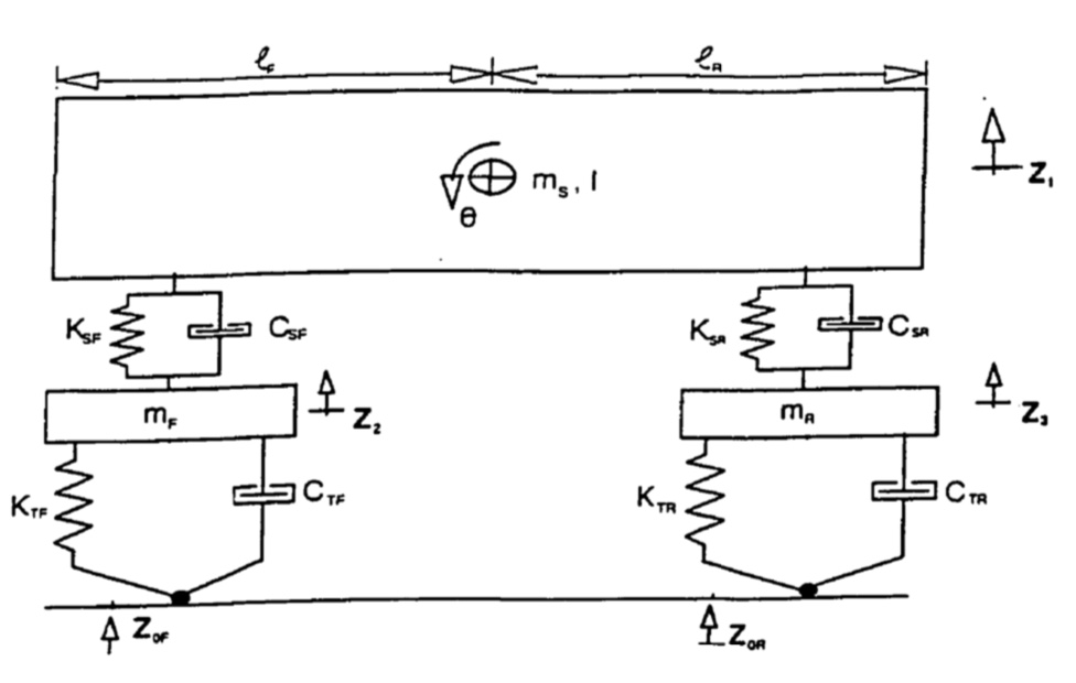
Starting from the top, the big rectangle represents the sprung mass of the vehicle and how it can translate vertically and rotate in pitch. Ksf is the main suspension coil spring (either just one or both fronts together) where K stands for the spring rate. Csf is the shock absorber parallel with the coil spring where C stands for the damping rate. The Mf is the unsprung mass of the front tires, wheels, axles, etc. Ktf and Ctf are the spring rate and damping rate of the front tires. Ctf is very small and is almost universally ignored, but not by Muluka. This guy kept it in his math, at least as far as I can tell by inspection of the equations he develops that represent the model. The Z’s at the bottom are the input displacements from the roads, i.e. bumps and holes. He uses mathematical forcing functions for the Zs that represent smooth, moderate and rough roads, specifically the roads in his area of Canada. Someone else had already collected that data.

Muluka then creates shock absorber models that are more sophisticated than most studies I’ve read. When he looked at typical truck shocks he found that they were 1) asymmetric, i.e. had different values for compression and rebound, and 2) had blowoff valves on the rebound side. Such shocks have characteristic curves as shown below in Figure 2 (his Figure 2.13).

Figure 2

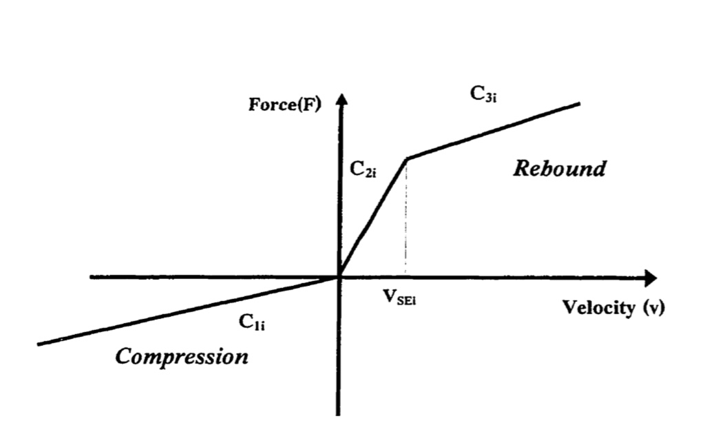
In Figure 2 note that the rebound is shown as positive, the opposite of what we normally see in shock dyno charts. (This is typical of many analytic treatments… the sign convention is opposite.) Also, we usually see the negative side of the graph folded over in an over/under manner, but academic papers rarely do that.

This figure throws us right into several of our questions. It has linear compression and digressive rebound with asymmetry. Cool!

Muluka’s Results

Muluka begins with symmetric linear damping in his quarter-car model, i.e. equal compression and rebound with no knees in the curves, and then later gets more complicated. With symmetric and linear damping he found that a damping ratio of only 10% had a huge effect on the Dynamic Load Coefficient (DLC) as compared to none. DLC is a measure of load variation at the tire. Muluka was interested in saving the pavement while we are interested in maximizing grip, but all the studies show that they tend to go hand in hand so we’re going to assume that DLC is a proxy for grip.

Muluka found that 25% to 30% of critical damping produced the best (minimum) DLC as shown in Figure 3 below, which is his Figure 4.2.

Figure 3

Increasing the damping above 25% doesn’t improve things though the DLC doesn’t get much worse either. Remember, this is symmetric and linear damping. No digression, regression, progression and no blowoff. He only goes up to 50%, but the trend indicates to me that even at much higher values, 60%, 70%, 80%, which we may want to use for transient response reasons, the theoretical loss of grip is minor.

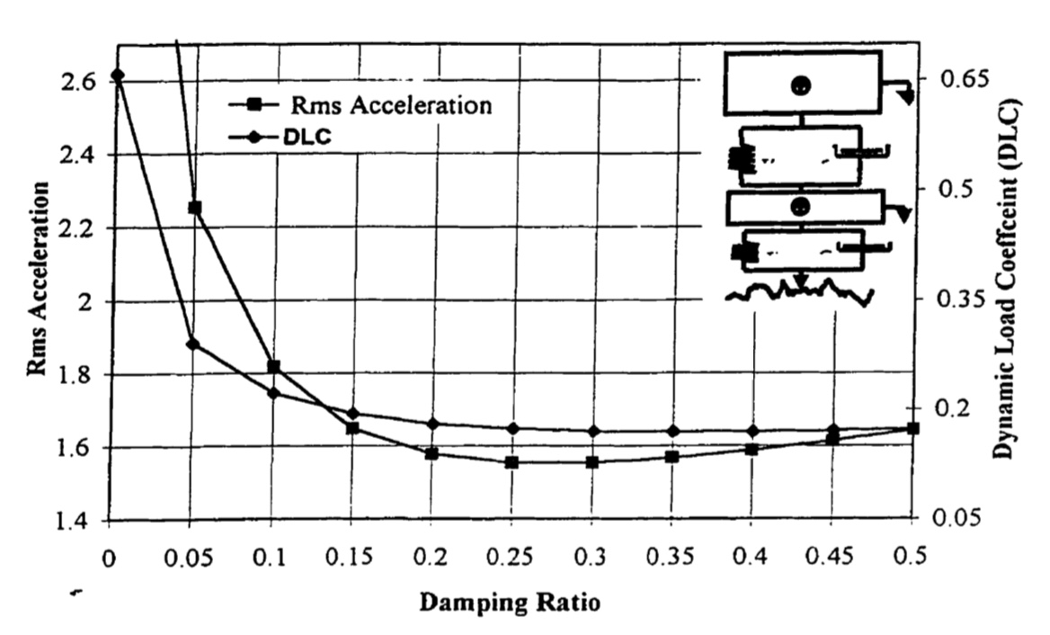
Then comes one of the most interesting charts in his entire study from our standpoint. In his Figure 4.3 which I have reproduced below as my Figure 4, Muluka varied the ratio of rebound to compression damping from 1:1 to 9:1, that is, up to 9 times more rebound than compression.

Figure 4

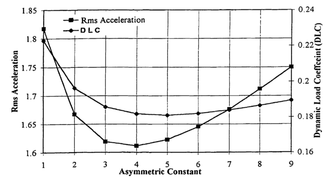
He found that the best (lowest) DLC values came for a ratio of 4:1, i.e. four times as much rebound as compression. The best ride, as represented by Rms Acceleration, was at 5:1. (RMS stands for Root Mean Square…sort of an average value.)

AFAIK, this is the earliest published analytical result supporting the widely used practice of weighting towards high rebound and low compression which was the nearly universal damping characteristic used since the dawn of the automobile. This provides a rational answer to Dixon’s question about asymmetric damping in the automotive industry I talked about in Part 1. Apparently Dixon, even in his 2006 2nd edition of The Shock Absorber Handbook, didn’t know about this result in Muluka’s thesis from eight years before. Since then there have been numerous studies which confirm Muluka’s results, i.e. more rebound than compression produces a better ride and better grip.

Does this mean we want 4X as much rebound damping as compression damping on our autocross car? No it does not. We must be careful not to jump to conclusions. I have a friend who received a set of expensive shocks that had 4X the rebound as compression. They were absolutely horrible, probably because the gross amount of damping was too high. The car may also have been jacking down terribly onto the bumpstops.

Can we ask why this result is what it is? You can ask, but that’s outside the scope of Muluka’s thesis. When you simulate with a model you get certain results. The question of why is separate. Not unimportant, but a separate consideration. It’s left to us to figure out the why, where the results might apply and whether the model is actually good enough to pay attention to in the first place. None of these questions have easy answers.

Next Muluka investigates optimizing asymmetric and non-linear shock damping. The result is very interesting.

He reverts to his more complicated full model shown in Figure 1. He uses the full shock characteristic curve as shown in Figure 2 where the rebound blows off at a certain shaft velocity. He investigates compression damping values that range from 5% to 20% of critical, which is low by our autocross standards, unfortunately. He looks at results at 80kph (49.7mph), 100kph (62.1mph) and 120kph (74.6mph) on a smooth road and a rough road. I will focus on the lower speed of about 50mph and the smooth road results. He finds the optimum rebound damping and blow-off velocity for each compression level.

 The results were that as compression damping rises rebound damping needs to drop or the DLC gets worse. When compression was only 5% the best value for rebound was a whopping 82% and no blowoff helped. After that the best rebound value moved linearly down as compression went up and you needed to blow off the rebound at a certain velocity. With 20% compression damping, rebound damping was best at only 60%. (The mean damping was about 45% of critical for best results.) These results are shown in Figure 5, which is reproduced from a portion of his Figure 4.1.

Figure 5

This inverse relationship between compression and rebound values may explain why very different shock valving strategies can produce similar results. In this study 10%/80% asymmetry produced the same results as a 20%/60% asymmetry. I can only expect that raising the compression damping further, as we do in autocross, would require additional decreases in rebound to prevent hurting DLC and thus grip. For instance, we may want much higher compression damping than would ever be considered on a passenger car or big truck for other reasons, such as in the pursuit of better transient response. I think what this does tell us is that as we increase compression damping ratios above 20% then we’ll probably find that we must decrease the ratio between rebound to compression even further than the 3:1 ratio Muluka ends at or we are likely to start losing grip. I note that Dennis Grant’ ‘s calculator produces an approximate ratio of 2:1 at recommended total damping levels of 65% of critical (bump and rebound combined) and that for FSAE cars KAZ Technologies recommends shocks with 50% more compression than rebound, flipping traditional damping asymmetry on it’s head. KAZ Tech also recommends a damping ratio of as much as 400% of critical, but only at extremely low shaft velocities. (They are double-digressive.) At higher velocities they reduce to less than critical. However, those shock characteristics appear to be intended for an FSAE car that also has a very different, non-traditional setup.

So, be careful and don’t take the numbers literally. This is not a model of your autocross car. What I’m attempting to take away from this are trends and basic truths, not specific values.

Finally, Muluka investigates a comparison of linear but still asymmetric shocks, i.e. shocks with no rebound blowoff, vs. his optimal damper with rebound blowoff as shown above in Figure 2. He shows that the optimal damper with rebound blowoff, at 50mph on a smooth road, reduces the DLC at the front by 30% and 21% at the rear compared to a linear damper. The effect is not quite so large on a rough road at low speed, but reverses at high speed. At high speed blowing off the rebound provided best results on a rough road and wasn’t quite so important on a smooth road.

My takeaway is that this last investigation indicates that no matter the level of bumpiness it is best to blow-off (digress) rebound damping at some particular shaft speed for best grip. If we assume that we’re going to digress the compression as well (not studied by Mukula but common in autocross) then this argues for a double-digressive shock characteristic.

This makes me feel good about convincing the owner of the car I’ll be driving next year to invest in double-digressive pistons!

More to come, I think.

*Update: We invested in double-digressive pistons and had them valved to a specification I wrote, using Dennis Grant’s on-line calculator. The car was so good at every event on various surfaces that we were never even tempted to turn one of the adjusters.

A Note About Understanding Technical Subjects, like Shock Absorber Tuning

Someone on the internet asked someone else for an easier to understand explanation or translation of my most recent blog post about shock tuning. I feel for that person, but there’s an issue. I want to illustrate the problem with the following quote from Understanding your Dampers: A Guide from Jim Kasprzak, available at kaztechnologies.com:

“In fact in the U.S. they are often called shock absorbers, even though they really don’t absorb shock!” 

I’ve heard this a lot. I may have even said exactly the same thing. As an engineer I think, Okay, this is technically correct, but is actually sort of an arrogant way to talk to college kids in an FSAE program, which is the intended audience. (I do understand that starting to teach by challenging assumptions is a valid technique. It tends to wake people up and prepare them for consuming a new idea. I do it all the time, so I don’t want to be too hard on ol’ Kaz. I hope he’ll forgive me.)

Of course shock absorbers do absorb shock in every sense except a narrow technical one. In fact, they turn kinetic energy into heat! Energy gets put into them and it (almost) magically disappears. You don’t have to deal with that energy any more. The spring, which is what Kaz and others want to call the “real” shock absorber, can’t do that. They give back (almost) all the energy they “absorb” and you still have to deal with it, just on a different time scale. Springs are time shifters! There, I created a more accurate description of what springs do. (Didn’t I?)

Anyway, when someone like me assails you with the quote above they’re falling back on a technical idea of “shock” of which the regular person is unaware. That idea is the rate of change of acceleration, technically called jerk. 

When you get hit by a truck as you cross the street you get “jerked”. You go from no acceleration to mucho acceleration very quickly. The rate of change of acceleration (the definition of jerk) is very high and that hurts. If you were dressed in a suit of springs the acceleration wouldn’t be so bad. As the springs compress they deliver all that energy of impact to you over a longer period of time. They time shift the energy. You might even survive, at least until those springs give back all that energy and launch you into the next county because only the “shock” was absorbed. You still must deal with all the energy of that impact, one way or another. Unless you have shock absorbers.

When your tire moves up and down for any reason, bumps, potholes, little ripples in the pavement or, God forbid, you turn the steering wheel, all the energy contained, released or transformed by the event goes into the mass of the car despite the springs and make it move.

Unless you have shock absorbers.

The next statement that follows the warning that shock absorbers don’t really absorb shock is usually something like “What shock aborbers really do is damp mechanical motion.” So, we special ones (technologists of whatever sort) have our special, correct word for them. We call them dampers!

When someone says this to the non-technologist has it delivered any useful information to them? I don’t think so. Not much, anyway.

But, wait just a second, you say, filled to the brim as you are with common sense. Don’t springs do that too? When the tire hits a bump doesn’t it get 1) jerked (see, I learned to use that word in a new way, you jerk) and 2) accelerated upward into the car? Doesn’t it start moving very fast and then it slows down and stops? Isn’t it the spring that stops it? Doesn’t the spring provide a force opposing that upward velocity and reduce the velocity and extent of that motion? Didn’t the mechanical motion get damped? So, isn’t the spring a damper too? 

Of course it is. Except… oh, never mind!

If you want to understand this stuff then you will have to get beyond the words and develop new, deeper and more accurate ideas. Specifically, you will need to gain some understanding of the theory of mechanical vibration of spring-mass-damper systems, which will be the subject of my next blog post. (I think.) It will take some work. It can’t be “translated” into easier to understand terms because common terms and ideas just don’t contain the necessary concepts and functions. Just like you can’t fully render Shakespearian ideas into the language of a 3rd grade nap-time story. The 3rd graders don’t have the necessary vocab, concepts or life experience. The have to grow up and learn a lot before they can comprehend, much less appreciate, the content of old Bill’s “stories.”

So, buckle up. Springs do more than one thing on a car and so do the shocks/dampers. And to give Kaz his due, he goes on to tell us what those things are. So, maybe you want to go read what he has to say.

Basics Of Shock Absorber Tuning

Smooth Ride or Best Grip?

Your car’s suspension is classified by engineers and dynamacists nerdy types to be a spring-mass-damper vibration isolation system. Most of the automotive world looks at this system and wants to know how to best provide a smooth ride for the occupants. They typically use a thing called the transmissibility factor to evaluate how good the system isolates the passengers from the not perfectly smooth roads which impress forces onto the tires. The basic question is, given a bad bump or pot hole, how much of the force (or displacement or acceleration or jerk) at the tire gets transmitted to the passenger? That’s given by the transmissibility factor and (and this is key) the value of the transmissibility factor varies with the frequency of the input disturbance.

It’s really kind of sad. The engineers long ago figured out how to provide an excellent ride. It turns out that 90% of the answer is the shocks. Unfortunately, by and large, the car companies have not wanted to spend the money to provide better shocks, so lots of cars, even luxury cars, give a pretty poor ride compared to what it could be. (Edit: Of course, good shocks can be very expensive. Examples for my Corvette with approximate retails costs are 1) OEM C6Z06- $600, 2) Koni 3013- $1400, 3) Penske/Ohlins/JRZ, etc- $4,000. How many people want to spend 10% of a car’s cost on just the shocks? Answer: Only us idiot autocrossers.)

Of course, passenger comfort is not worth much if the driver can’t control the car. So a subset of these investigations aims at what it takes to assure controllability. A subset of those investigations is concerned with how to maintain best grip from the tires in the guise of least force variation at the tire’s contact patch, which is what we autocrossers are mostly interested in. Well, it turns out that maintaining best grip by minimizing contact patch force variation is not totally different from providing best comfort. In fact, they tend to go hand in hand to a significant extent. This is good for racers. Otherwise the racing world would have had to invent all the math themselves!

Transmissibility and Tire Force Variation

A mathematical factor called transmissibility is a key component in these ride quality, car control and grip maintenance investigations. Transmissibility is how much of the force input from a bump gets through the suspension and into the body of the car. We will discuss transmissibility in-depth in Part 3 of this series, but for now we just need to know that low transmissibility equates to a good ride and basically assures low tire force variation.

Transmissibility is highly dependent upon the relationship between input force frequency and the natural frequency (Fn) of the spring-mass-damper system. What that means is that how much force gets into the body will be different for different input frequencies. For instance, a series of small bumps, say one every half-second, might not be felt much at all. The transmissibility of that input would then be near zero. But, if those bumps were slowed down to hit the tire every 1 second, we might feel a very annoying vibration. The transmissibility of that bump frequency is then quite high. The Fn for each corner of the car is easily calculated if you know the masses, the spring rates and the damping rates. (The damping rates are how fast you take energy out of the system after you start it moving with an input. In a basic sense, that’s what shocks do.) Generally the front corners of the car are basically identical as are the rear corners, but the front and rear Fn values may be slightly different from each other.

Engineers design most mechanical systems to operate far away from the system Fn if at all possible. With cars and their suspension systems it is not possible. As we drive the car we are guaranteed to have inputs below, at, and above the system Fn, either from what the driver does or the world does. This is because we start from zero, i.e. one large-amplitude strike from a big pothole, all the way up to the short but sharp high-frequency input from a cobblestone street. To handle the whole range the Fn will necessarily be somewhere in the middle Let’s explore the input from driving a slalom, that signature autocross maneuver.

Slalom Input Frequency

A slalom is driven at about 1.1s per cone in my Street class Corvette as detailed in a previous post here. An interesting fact is that the distance between the slalom cones doesn’t matter much. It always takes about 1.1s. (This is a feature of the fact that the longer the distance between cones the faster we can travel, so the time between cones stays almost constant.) A complete cycle from left to right cornering is accomplished in this 1.1s. Therefore, the average excitation frequency input to the suspension by a slalom maneuver is the inverse, or 1/1.1s = 0.9Hz.

In a stiffer (non-Street) car the slalom time could be (will be) less, maybe about 0.9s, also shown in the post linked above. Then the frequency is 1/.9 = 1.1Hz. A little faster.

I have no idea what the slalom time is for something like an FSAE car, but it might be even lower, which means again a slightly higher input frequency.

OK, so what? The what is that we really don’t want the input forcing frequency to be near the natural frequency, Fn, of the suspension. There’s a feature of spring/mass/damper systems called resonance where the system motion can actually increase and go out of control. We control resonance with damping. If the damping at the associated shaft velocity of the shock absorber is very low, as it typically is with OEM or cheapish after-market shocks, or even zero, like with a blown shock, then wacky things can occur. The least of the bad things that can occur is a loss of grip. The worst is total loss of control of the car.

Any guesses as to what the natural frequency is at each corner of a typical passenger car on the road today? 1.0Hz to 1.5Hz.

Houston, we have a problem.

Example: Once I had one blown front strut on my SUV and didn’t know it. I pulled out from the Tee at the end of my street, turning and accelerating quickly onto the busy road, as you must do since the sight lines are really bad and the cars come fast up the hill even though they can’t see over the top. I nearly lost control of the car and thought for a moment I was going over the curb. I went back to the garage and found a puddle of fluid on the floor. I had trouble controlling the car on a city street just from accelerating and turning through a single corner with impaired damping on one strut. So, having a sufficient amount of damping at the Fn of the suspension is critical for maintaining control of the sprung mass of the car as well as maintaining grip at the tire patch.

Also note that whatever damping is provided by the shocks tends to change (decrease) the dynamic Fn. It’s not much for small amounts of damping, but significant for large amounts. As much as 40% according to one paper I read at 80% of critical damping. (We’ll get into critical damping at some point later on.) So, large amounts of damping can do two things simultaneously, 1) make the problem worse by lowering the dynamic Fn closer to the input frequency, and 2) make the problem better by damping any bad effects. What happened when I added lots of damping to my Corvette’s 1.5Hz Fn by installing those high-dollar revalved pimp shocks? Perhaps it went from 1.5Hz down 30% to 1.0Hz, right at the slalom input frequency. Sheesh! Ah, but what’s a lot of damping doing to the grip? Turns out that depends on a lot of things I’m not ready to go into here but I will say this: for frequencies below Fn x the square root of 2 (1.414 for the non-nerdy types), which would be 1.5 x 1.414 = 2.1Hz on my Corvette more damping generally decreases tire force variation and thus increases grip at the same time it increases control. Finally, something working in our favor! (And a justification for those pimp shocks.)

Guess what happens if you add damping above Fn x the square root of 2? Hint: grip doesn’t improve with more damping for inputs above that limit, which contains basically all bumps and even some of the driver induced effects for a Street-class car. You have to have some, but really not very much at those higher frequencies.

Increasing Fn numbers from the factory (i.e. stiffer suspensions) may be one reason why modern sports cars with Fns of ~1.5Hz (or higher) are so much better at autocross as compared to standard cars or older sports cars that were significantly softer. (The ride, however, is generally worse, because stiffer springs are cheap but better shocks are not.) This also goes some way to partially explain why the addition of a much stiffer FSB (Front Sway Bar) for a softly sprung car in Street-class autocross is so necessary. The stiff FSB increases the effective roll stiffness during transient events, moving the dynamic Fn higher and a safe distance away from the input frequency. So, the car with the stiff FSB gives us faster response and more control. (We won’t mention understeer here, but you can think it.)

In classes where you can change the springs and get Fn anywhere you want then a super-stiff FSB is no longer necessary to avoid inputs near the suspension resonance nor to provide acceptable front-end response. Nor is it required to contribute as much to roll control.

Even if Fn is well above the input frequency, the analytical studies say we still need good damping at the input frequency to limit force variation at the tire patch and thus maintain good grip. That’s why significant damping forces at 1Hz, for instance, are necessary. We only get that in good shocks properly valved, i.e. I can almost guarantee that your car didn’t come from the factory that way. But, we don’t see frequency on our shock F-V plots do we? We see shaft velocity. So, what’s the shaft velocity that corresponds to our 1Hz input in a slalom? It’s not difficult to estimate.

Maneuvering Shock Shaft Velocities

If the shock shaft travels a total of 3″ in a 1s slalom then the average velocity is 3/1 = 3in/s. This assumes that the shock shaft moves 1.5” on either side of the static position, which seems reasonable to me for a stockish car. (Note: this is in roll, not heave.)

If the shock shaft travels only a total of 2″ in 0.9s, which might represent a non-Street autocross car that’s low and stiff then the average velocity is 2/0.9 = 2.2in/s.

The peak velocities will be higher, of course, since at each end of the stroke the velocity is zero, but the peaks are limited if the shock provides significant damping. Shocks slow down the shaft velocity by providing an opposing force while increasing the rate of weight transfer. If that’s not clear to you, go read this old post.

This is good support for Dennis Grant’s claim in Autocross To Win that driver-induced frequencies are mostly up to 3in/s so you need to valve the shocks with this in mind. DG provided shock shaft velocity data from three autocrosses in his Street Modified car to support his point.

On the other hand this is poor support for Ross Bentley’s claim (in Shocks For Drivers, pg.12)  that driver-induced shock shaft speeds only range up to 1 in/s. Bentley provided no shock shaft velocity data to support his point. I think he might have misunderstood the data he was looking at. For instance, it may very well be that the majority of the time, when looking at a shock velocity histogram, the shocks operate below 1in/s. Especially for a race car on a smooth track. That this is true is easy enough to verify on the internet and I have done so. However, this would say nothing about what velocities are the most important during specific maneuvers, such as corner entry and exit or, God forbid, an autocross slalom.

One last thought. Even if we are convinced that we need significant damping at low shaft velocities to maintain good grip when maneuvering we are still faced with another choice: do we provide the damping equally split between bump and rebound, or do we weight it one way or the other? Traditionally almost every analytical study you can find assumes equal damping in both directions. (Makes the math so much easier!) Just as traditionally almost every shock you can find that’s ever been fitted to an automobile since it’s invention provides more rebound than bump, sometimes many times more. Why? In the Shock Absorber Handbook, 2nd Edition, 2006, the author John Dixon states, “[I have] questioned various vehicle dynamicists informally on this point, and received less-than-convincing replies. Generally, there is a belief that there is a simple explanation, but this was not actually forthcoming.” But 2006 was back in the dark ages, man! I’ve found some more current data of interest. We’ll be delving into this question in the next installment of this series.

Let’s Get Straight About Late Apexing- 5 (and Final)

In part 1 I wrote about three definitions of late apexing. By the time we got to part 4 I think I’d muddied the water a little bit. (That happens when you haven’t written each section before publishing the previous one.) So, let’s get it straight once and for all by slightly revising the three definitions:

Definition 1: An apex location that’s beyond the geometric center of the corner.

I don’t think we need to add anything more.

Definition 2: An apex location that’s beyond the accepted correct apex location.

This definition applies when people think that there’s one and only one apex location for a corner. OK, maybe it changes in the rain, but basically it’s the same for all cars.

Definition 3: An apex location that’s beyond the actual, correct apex location, understanding that the correct apex location will be unique to each particular car and situation.

Not much difference between 2 and 3, but the difference is crucial. Def 2 carries with it the implication that a single correct apex location exists based on the geometry of the situation, taking into account what comes before and after the curvy part of the turn itself. For instance, many have thought for the last few centuries that the length of the straight after a corner has an effect on the proper apex location. This has always been false. Many have also thought that the speed of entry, if limited by the preceding track geometry, has an effect on the proper apex location. This is correct. In fact, we find this ALL THE FREAKING TIME in autocross. Let me illustrate with an example taken from a real autocross event, not a made-up situation. Or, at least, not completely made up. As in all real-life scenarios it will be necessarily more complicated, but there may be multiple interesting lessons here to justify writing all these words about something I don’t even believe in, i.e. the concept of late apexing.

In Figure 1, below, we have the finish section of the East course at Solo Nationals in 2014 named Over The Falls by Jeff Cox, the designer. It was my first Nationals, in someone else’s car and before I knew much of anything about line theory. (What I thought I knew was mostly wrong.)

Figure 1- 2014 Solo Nationals Finish, East Course

First of all, recognize that the entry to the Over The Falls section is very fast. You accelerate hard from the top of the figure downward. Where to brake? Where to transition from turning right to turning left? (This is, by definition, a chicane because you can’t optimize the right turn separately from the left turn.) The key question in my mind was where to apex the left turn toward the finish.

I really had no idea.

Why don’t you look at it and decide how you would approach this section. Below I’ll show you what I actually did. Each run was different! In my confusion I seem to have bracketed the possibilities in my three tries at it. Please do learn from my ignorance.

To complicate matters the Corvette I was driving was set up very differently from my own. It wasn’t as over-tired as mine (so it wasn’t mushy) and had high-dollar double-adjustable shocks valved and set to make it handle like a kart. Never before (or since) have I driven a Corvette that could transition like that one. The downside? Less ultimate grip than my car. It was like driving on a knife-edge and very difficult (for me) to drive without provoking an oversteering slide. The owner, who won his first national championship that week, kindly warned me after our runs on the practice course that I needed to control my overly fast hand speed, but that was not advice I could easily implement on my first-ever Solo Nats runs.

On the first run I started slowing early, somewhere near the location marked BP (braking point) in Figure 2, below. This allowed a safe and fairly rapid turn of the wheel at the transition point, TP. I wrapped tightly around the two inside cones, apexing about in the middle at the big red X. From there, being so slow, I could start adding throttle and accelerate toward the finish. Cone 621 was never the least bit in play.

Figure 2- 2014 Finish, Run 1

Seem reasonable? It felt very slow. I think it was slow.

This method guaranteed that I fell below the limit very early, the speed at the apex was very low and I used mostly just the power of the engine to propel the car toward the finish. The turn I executed had a very small radius, severely limiting the time during which the tires were pushing the car at high lateral acceleration toward the new ideal direction. In short, I made the mistake of not using all of the available “track”.

At least I didn’t slide (too much) or spin at the transition point, which is the only saving grace for this conservative (scared to death) approach on the first run. In fact, this run turned out to be my fastest overall, setting me into 9th place of 28 drivers on day 1, but not because of how I executed this section.

On the next run I made the opposite mistake, as shown in Figure 3.

Figure 3- 2014 Finish, Run 2

I entered much faster, getting on the brakes late and soft because of continued fear of losing control during the yaw transient point, which thus became more separated from the braking point in both time and space. As a result of the soft braking the car carried way deep toward the horizontal wall of cones to the left of cone 621. My apex was somewhere near the big red X, after which I struggled (very slowly) to get around cone 621. I don’t know which was slower in this section, run 1 or run 2. Both felt awful.

On run 3 I think I did it closer to correct. See Figure 4, below.

Figure 4- 2014 Finish, Run 3

This time I got max on the brakes about point BP, even though I was already turning right pretty hard. I transitioned at the correct location, TP, while still hard on the brakes and managed, somehow, to not let the yaw moment create a spin. The apex was about at the big red X and was at a higher speed than both previous runs, but especially higher than run 1. I smoothly added gas from there. I barely made cone 621 which, these days, tells me I was doing it better. This better-optimized exit used all the space (track) available.

Starting from TP the lateral acceleration began building up, maxed out at the apex, but continued to help beyond the apex as the car turned toward the finish. Do you understand that the direction of this lateral acceleration is always tending to aim (left) toward the finish? It’s maximum magnitude is double what the engine could produce in that car. That’s why you want to use “all the available track width” to most efficiently add the engine capability after the apex and to best use the lateral acceleration capability of the tires both before and after the apex to push the car in the new ideal direction which, in this case, is toward the finish.

Unfortunately, the third run was not the fastest overall, though the final section felt much better. We got bit by overheated tires. That September day in Lincoln was unseasonably hot and my overdriving didn’t help the cause. After we both got slower on our second runs we realized what was happening and draped towels soaked in ice-water over the tires. It was too late. The carcasses of the tires were already too warm. In spite of each of us feeling like we drove much better on our third runs we both went slightly slower again. We stood on our first runs. Luckily, it was enough to give my co-driver the lead going into Day 2. He managed to very slightly again beat the fastest Honda S2000’s on the Day 2 course and take the win. This was back in the days of parity between non-Z06 C5 Corvettes and S2000s in B-Street when high-performance 200 Treadwear tires were just getting started. Those tires couldn’t put power down very well when exiting a corner which invalidated much of the Corvette power advantage. (That all changed when the Bridgestone RE71R came out.)

I contend that if the entry to this section had been different then our correct apex location would be different. Imagine that the course design causes us to take the path shown in Figure 5, below, approaching from the side and that the car’s speed is slower than before.

Figure 5- 2014 Finish Alternate Path

Now the transition point, TP, is earlier than the BP, which makes things easy. (We much prefer to stay on the throttle during the transition and then brake as the steering wheel crosses back over center.) So, no problem to now treat this as a standard corner of approximately 160 degrees once we are turning left. (We intentionally created a chicane on entry to get some angle, as we so often do in autocross, because it gets us through the corner faster by modifying the horrible pinched entry that this mythical course designer (moi) intended for us.) We apex somewhere about where the red “X” is located, about the same as in Figure 2, and add power from there to the finish.

My point is that the location of the apex is sometimes highly dependent on the speed of entry. If you accept this then you have to also accept that there is no such thing as a single, correct apex for any particular corner. Just the difference in the power to weight ratio of various cars is clearly enough to affect the best apex location, angle and speed even if only because it would affect the entry speed in a situation like this. Grip level also affects the apex, especially when you bring non-linear aerodynamic downforce into the picture. That also means that if the grip level of the surface changes, such as from a morning to afternoon temperature change, rain shower or any other cause, then you may have a new apex. For every corner on the course!

I hope you now have a clear idea of Late Apexing Definition 3: An apex location that’s beyond the actual, correct apex location, understanding that the correct apex will be unique to the particular car and situation.

Why would you ever take this type of late apex per Def 3, except by mistake?

Remember I said I don’t believe in the concept of late apexing? Let’s get into that now. I previously defined an apex as having three components: a location, an angle, and a speed. How is it useful to think about the concept of a late apex when it refers to only one of the three components, the location? Once we realize that an apex is not simply a location then I don’t think it is.

I’m sorry this has become so complicated, but I really do believe that, in theory at least, we have to determine the location, the angle and the speed for the location of minimum speed in any particular corner. At least I didn’t change that… the location of minimum speed is still the apex! Just figure out how fast you can or ought to be going at that point as well as the angle of the car to optimize the exit and you’re all done. Easy peasy.

One last thing: it’s fairly common in autocross, because of the interconnectedness from feature to feature, that we might enter a corner, say the approximately 160 degree corner shown in Figure 5, well below the correct speed at the apex, that is, the speed and angle at which we can rather quickly ramp up all the engine power. (This is exceedingly rare at race tracks for most cars.) If so, then we may be accelerating all the way through it in order to obtain that correct apex speed. In that case there’s no braking point! If you’re turning the car hard, but never have to slow down between the entry and the exit of a corner, is it still a corner? Not really. Brouillard, in his book The Perfect Corner 2, calls such situations “full-throttle corners” and has a special rule for them. I think that in autocross we encounter many such situations. Maybe we can’t be at full-throttle, but we may be using significant throttle to accelerate and there’s no braking point to be found. If you don’t have to brake there’s no corner in the standard sense and standard rules no longer apply. In that case I recommend paraphrasing a previous NFL team owner: Just get there quick, baby!