Autocross Season Prep Gets Started

Prep for the 2016 autocross season started this weekend. A few pictures to show the plans and progress.

First up, new rubber: RE71Rs in 265/275-18. They’re so clean and sticky if it was summer they’d catch flies.

L1030768

New Bridgestones

All disks have been sanded, ready for bedding-in new pads, Carbotech Bobcats that come painted red. I’ll replace the brake fluid as well.

L1030760

Sanded Brake Disk with New Pads in the Caliper

The Pfadt/Ohlins shocks are reinstalled. No changes since RE Suspension worked on them last year. I’ve routed the line to the remote reservoirs a little differently than last year to better keep it away from any sharp edges. The upper right A-arm bushing has migrated a tad, but it should be good for another year.

L1030762

Pfadt/Ohlins Shock Rebuilt by RE Suspension

The shock remotes are again strapped to the front roll bar, but reversed in orientation from last year. If I lay down in front of the car I can just reach them to turn the adjuster knobs.

L1030767

Most modern roll bar bushings don’t really need any lubrication, but to reduce friction to a minimum I cleaned and lubed them with Energy Suspension super-sticky grease intended for polyurethane bushings. I noticed that the inner surface of the bushings have circumferential ridges that seem like they will hold some grease in place quite well. I don’t think this stuff will wash out.

L1030765

Cleaned & Lubed Roll Bar Bushing

After the rears are finished, I’ll get the car aligned and corner balanced. Then, I’ll disassemble the driver’s seat again and figure out what’s broken in it this time.


2016 Plan: Improve Transient Response

I have a simple goal for the near future: do better at Dixie Tour, the first National Tour event of the year.

I’ve always done poorly at that event, held for many years at South Georgia Motorsports Park near lovely Adel, GA. I think at least part of the problem has been the site: it’s a long, thin parking lot. As a result, the courses have been similar, transient-heavy things. Wiggle your way to one end, turn around and wiggle it back. Almost a constant speed. Not much of anywhere to use much power. Not especially good for a Corvette against S2000s and MSR Miatas. In fact, in 2012 Jadrice Toussant won B-Stock in an S2000 with a time that would have been 3rd in Super Stock. He beat every Lotus, every GT3 and every Z06 except for Strano and Braun. Now, Jadrice is a heck of a driver and National Champ and he flat tore it up that day, but I think the course had something to do with it.

Here’s what it looks like. You can even see some tire marks.

SGMP

South Georgia Motorsports Park

So, the plan is to improve transient response. Mostly to see if I can do it and maybe do better at Dixie.

Two years ago I concentrated on maximizing lateral grip. Then last year I got some better shocks that I’d hoped would improve transient response via higher low-shaft-speed compression damping, but I was still focused on lateral grip. It worked to some extent, but not enough to place in the top 3 in class at Dixie. ( I was a miserably slow 4th.)

Before I start making changes, I figure I should review what I think I know about what happens when you turn a car and what factors control the transient response. So, I tried to write it down. (You’ll note that I like to start an analysis at the very beginning.) I focus on the front of the car.

  1. Turn the steering wheel. (We all do this pretty well, I guess.)
  2. The tires turn to an angle with respect to the car direction.
  3. Due to friction provide by gravity and proportional to the weight on the tires, the tire contact patches deform and twist, producing slip angles and lateral forces at each contact patch.
  4. Tire patch lateral forces transfer to and act on the sprung and unsprung forward masses and do two things: change the direction of the front of the car by creating a lateral acceleration, and create lateral weight transfer.
  5. Lateral force acting at the unsprung mass CG acts to instantaneously create weight transfer (like on a kart) and tends to reduce the ultimate lateral acceleration possible as weight is transferred from inside tire to outside tire, reducing the total contribution of all the tires added together.
  6. Lateral force acting on the sprung mass through the roll center rolls the sprung mass on the springs and bars to create (what Dennis Grant calls) elastic weight transfer, neglecting any small lateral translation of the CG. (I’m going to simplify things and neglect jacking force, or Geometric weight transfer, again per Dennis Grant, as it is small in the Corvette because the roll center is close to the ground.) The amount of roll does not affect the [total] amount of weight transfer. Update: I think I wasn’t clear, as Mr. Glagola has pointed out. What I mean is, the total amount of weight transfer is not dependent upon roll stiffness. Yes, the weight transfer build-up is proportional to roll angle, but that is because both the roll angle and the weight transfer are proportional to lateral acceleration. When the car gets to it’s final roll angle, whether it be 1 degree or 15 degrees, weight transfer is complete.
  7. Compression damping turns part of the sprung mass roll, during the roll transient, into increased downward force on the outside tire contact patch. This temporarily increases the lateral force capability of that tire. (It also turns some of this roll energy into heat, which leaves the system, so it never gets into the springs or bars.) This is why high levels of low-shaft-speed compression damping assists transient response. It acts as if the spring temporarily got stiffer. At the extreme it would allow the outside spring to compress only very slowly. In a slalom, with enough compression damping, very little roll might have time to actually occur before the car is asked to change direction again.
  8. Rebound damping on the inside wheel also resists sprung mass roll during the roll transient and once again some energy is turned into heat. The rebound force tends to hold back the roll of the sprung mass. To do this it picks up weight from the inside tire and tire patch, which tends to decrease the lateral turning force produced by that tire. In the extreme case the tire might leave the ground as the body rolls and the wheel follows. (I don’t think any shocks have that much rebound damping, but it could be done. If you were an idiot. Or an engineer trying to prove a point. Or some mixture of both, as is the usual case.)
  9. Roll of the sprung mass extends the inside spring, thus reducing the load on the inside tire. Roll compresses the outside springs, increasing the load on the outside tires. Without shocks, achieving maximum cornering force is delayed until the sprung mass roll is complete, if for no other reason because the outside tire doesn’t get to it’s final, proper camber until then. By resisting roll both rebound and compression damping forces speed up weight transfer across the front axle, getting the car into a cornering attitude faster and with slower roll, and thus less total roll during the transient. In this way, we don’t have to wait for the sprung mass to roll to it’s maximum before achieving high lateral cornering forces, though reaching the maximum cornering force is probably not going to happen. I suspect this will increase the maximum achievable cornering force when time is short, such as in a slalom. However, almost all of the increased energy in the compressed spring will be delivered back into the sprung mass when the turn is reversed, helping to roll the car the other way. The shocks absorb some of this energy in both rebound and compression, turning it into heat, and thus assist in keeping the car controllable during repeated maneuvers.
  10. All roll twists the front sway bar. Like the springs, most of the energy absorbed by the sway bar is given back when the car is turned the other way. Therefore, during transient maneuvers the energy put into the bar during whatever roll occurs wants to come right back out and roll the car the other way. Once again, shock rebound and compression damping absorbs some of the energy, keeping the car from rolling uncontrollably during repeated maneuvers. (Unless you are a certain production SUV and fail the Scandinavian Moose Test.) By limiting maximum roll, and thus camber loss, the sway bar may increase maximum lateral G forces in a sweeper by keeping all tires working better than otherwise. The sway bar also slows the rate of roll, assisting transient response. [However, the sway bar, unlike the springs, acts across the car to create an increase in the total weight transferred from the inside to the outside, which tends to decrease total lateral G capability.] Update: I now believe the statement in brackets to be false. In softly sprung production cars it is almost always better to limit camber loss by limiting roll with stiff sway bar(s). However, it may be that during the roll transient of a production car (with soft springs) it may be better to trade sway bar stiffness for an increase in shock damping, especially compression damping, in order to limit weight pulled off the inside tire.

So, based on this assuredly imperfect understanding of what happens when a car turns, I’ve come up with an action plan:

  1. Choose a tire known for it’s lateral stiffness. The RE71R is known to be one of the stiffest & most responsive. That’s what I’ve been running.
  2. Properly support the tire with a wide-enough wheel. I’m  down from an oversized 275mm to a less-oversized 265mm this year on the required 8.5” wide front wheel.
  3. Increase support to the tire with air pressure. The past two years I found a relatively low pressure was needed to maximize lateral grip in sweepers. This year I will test using higher pressure in front to maximize tire support and hopefully produce faster transient response at the contact patch.
  4. Keep using significant toe-out on the front tires to more rapidly establish a bigger slip-angle on what will be the inside tire in the turn. This worked well last year. This allows the inside tire to more quickly create a lateral force, pulling the front end of the car into the turn. As the weight shifts to the outside tire, it has now developed a good slip angle and can really drive the front end into the turn. Because of weight shift, the inside tire is of lesser importance by then. I reset the toe before driving home after out-of-town events. The poorer front-end response with no toe-out is palpable.
  5. Test using the softer setting on the front anti-sway bar. The final roll angle may be less important because the final roll angle will not be reached in a slalom situation. I used the stiffer setting last year on a stiff bar to maintain proper camber of the tire during sweepers. For best transient response, it may be better to reduce the stiffness to reduce weight transfer off the inside tire. It may be possible to keep the inside tire working longer in the initial part of the turn. I will try to figure this out at an upcoming Test & Tune event. Update: As noted in an update above, the basis of this is false. So, I won’t be reducing roll bar stiffness, at least not for this reason. I might reduce roll bar stiffness for balance or stability reasons.
  6. Test with the shocks adjusted for higher front rebound and compression damping than used before.

Of course, all this may completely unbalance the car and I’ll be even slower than last year. I expect I’ll learn some things either way.


The Really Weird Thing About Modern American Autocross- Revisited

Notice of update: I realized after publication that I’d used an entry speed of 55mph rather than the 50mph used in the previous installment of this series. So, I’ve got back up at 12:30 A.M. and changed it back to 50mph. Didn’t make much difference to the results data and no difference to the conclusions. (I also tried to make Figure 4 less of an eye test.) My apologies to the over 400 of you who have already read this in the first few hours of publication.

I received some good comments on the earlier post “The Really Weird Thing About Modern American Autocross- Part 2”. Charles Krampert, for one, pointed out that I wasn’t taking into account the angle one must drive after leaving the first cone to be set up for the same radius around the next cone. I finally got some time to put that extra turning into the graphics and the spreadsheet. Turns out it makes a significant difference.

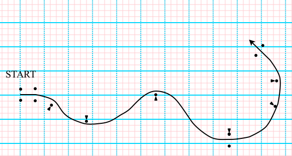
Remember that I’m trying to figure out what radius is fastest around a cone, depending on the acceleration capability of the car. (If you don’t remember, you might want to go back and read the earlier posts.) I assume an infinite procession of cones 150 feet apart which require a nominal 90 degree change of direction around each cone. I also assume 1.2G lateral capability and 1.0G braking, which is typical for many street-class autocross cars. The basic idea is shown in Figure 1, below.


proper path

Figure 1

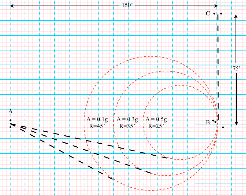
More specifically, Figure 2 shows what I’m analyzing and, in fact, represents the actual fastest radius for a car with 0.3G acceleration capability, namely a radius of 15 feet.
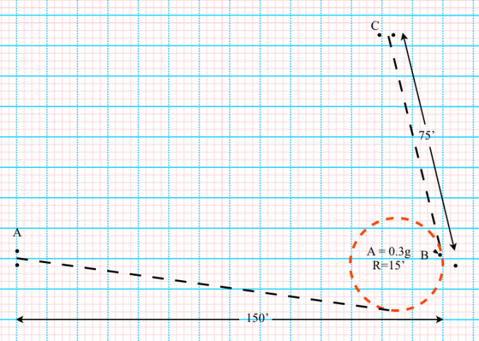
tic3 .3g curve

Figure 2

From A to B the car has to take an angle to the outside of B to produce the 15 foot radius. The car then has to go more than 90 degrees in order to exit B to allow it to go around the next cone, 150 feet away (not shown) at the same 15 foot radius. I  calculate the time from the start at A, going 50 mph, to the finish at C, 75 feet beyond B.

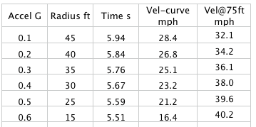
It turns out that considering the extra turning to get to the proper angle for the next cone reduced all the answers. Here are the results, with the old radii results, then the new radii results. The remaining data is all for the new radii.
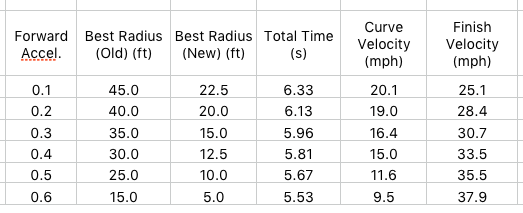
TIC3 results updated.png

Figure 3

We can make a few observations:

-As before, as the accelerative capability of the car goes up, the best radius goes down. This agrees with what most people think.

-As before, we see an immediate issue with the curve velocities: they are too low for most cars to accelerate strongly from in 2nd gear. More on this below.

-The new best radius values are lower and more compressed over the G range than calculated previously. The extra turning required to be oriented correctly for the next cone greatly penalizes big arcs. A lot of time is lost going around at minimum radius at minimum speed. This goes a long way to answer the doubt I had expressed about the large radius values that the previous analysis showed as best and which I have not seen being used in practice. (I’m a big believer in the idea the most experienced people are doing it  mostly right most of the time.) By the same token, if you don’t have to turn the car as much for the next cone you are better off with a somewhat larger radius. The data seems to be very sensitive on this point.

The very low curve velocities associated with very small turning radii mean that there’s a big problem with using this data to make firm conclusions. I began this study thinking that I was using acceleration ranges that were typical of peak torque in 2nd gear. What this has shown is that we can’t think of it that way. The best theoretical radius is always too small. Instead, we have to think of the acceleration that is actually available at the particular curve velocity required by such small radii.

For instance, my BS Corvette can accelerate at 0.45G at peak torque in 2nd gear. But at 25 mph it may struggle to reach 0.3 G. The results chart says the best radius for 0.3G is 15 feet, but my car will only be going 16.4 mph around a 15 foot radius and will really struggle to accelerate in 2nd gear from that low speed.

On the other hand, what this data may be telling me is that I’d be better off taking a smaller radius and downshifting to 1st. I know, this is sacrilege! I’m going to lose roughly 0.2 seconds when I upshift and probably lost some time downshifting as well. Will it ever be worth it to downshift?

Looking at the sensitivity of the results may shed some light. Here is the spreadsheet set for 0.3G in Figure 4, below.
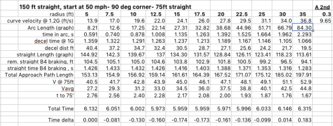
TIC3 graph updated

Figure 4

Looking at the Total Time row you can see that the minimum time is 5.959 seconds underneath the 15 foot radius column. That’s how I get that 15 feet is the best radius for a 0.3G car… by comparing it to the results for radii both bigger and smaller. It’s a brute-force optimization technique. (It’s also 5.959 seconds underneath the 17.5 foot column, so the real minimum is somewhere in between. I just chose one.)

If I change the A 2nd acceleration parameter in the upper-right corner all the columns recalculate and I find the minimum time for that G-level. I graphically determine the arc distance and straight length within the columns for each case.

Now, how far off of that best 15 foot radius do I have to get to equal a 0.2 second downshift loss? I’d have to go beyond a 30 foot radius before losing 0.2 seconds. But, the bigger radius I take the less I will need to downshift. If we assume that at a 30 feet radius I definitely don’t need to downshift, then if I choose to take a 15 foot radius and do downshift I am, at best, breaking even. I think this confirms the majority view that downshifting with a relatively slow-shifting car like mine is almost never a good idea. The corner’s gotta be really tight to consider it.

If we consider a motor with really poor low-RPM torque, say an S2000 that will drop out of V-tec, then no way it should take the smaller radius. Unless…

Here’s the real rub and why I entitled this series of blog posts the way I did. For corners where the car is forced by the course design to take a very tight radius S2000 drivers have learned that it is better to downshift to first when I would not in my Corvette. At least that has been my observation after competing against them the last few years. They “know” that they lose too much trying to get off a slow corner in 2nd. (When I see an S2000 struggling to accelerate below the V-tec RPM switch it just warms my heart!) I think we all know that there is some point that we should shift to first gear if the corner is very tight.

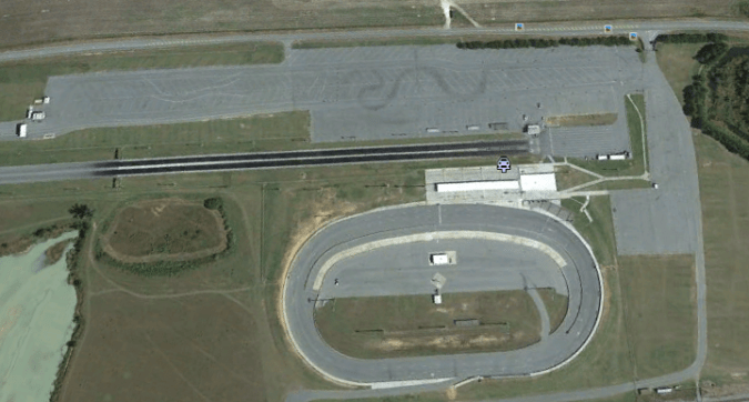
Let’s level set and get our bearings. When do we know that it is definitely advantageous to downshift? Pin cones. All of us who have done 180-degree pin cones know that the best way to take them is absolutely as tight as possible and downshift to 1st by all means. (Thank you, Randall Wilcox.) We never see these at National events, but they had one at every event in Nashville at the Superspeedway lot that I ever attended and we have them quite often in Huntsville when we run at the old airport. I’ve done a lot of those suckers.

Alternatively, when do know we would never downshift? How about a 45 degree turn? No way we would downshift to first. We all know that we cannot even create a radius small enough to force the car so slow to even think about downshifting.

So, somewhere between 180 degrees of turn and 45 degrees of turn is a middle ground where it may or may not pay to downshift from 2nd gear at autocross speeds. We happen to be concerned here with 90 degrees and somewhat more, so we are probably right in the no-man’s land.

Of course, there’s another issue with downshifting. Can you get the power down? If you can’t get enough power down to create the fantastic acceleration promised by 1st gear, no point in downshifting. Also, as soon as the rear end steps out you’ve lost 0.2 seconds, or more.

All this implies that, in certain situations, the right radius for a car on R-comps is not the same as the right radius for a car on street tires. It also means that as tires get better at putting down power, as we saw with the Bridgestone RE71R last year, it may affect the proper radius. Yes, autocross is complicated.

What about dual-clutch transmissions? What if you can downshift and get 0.7G in 1st gear even in a relatively low-powered car and then lose next to nothing when you upshift to second? I think this data says that for large degree turns you should consider braking down to a very small radius and downshift, within the limits of you car’s ability to put power down. You might even alter your whole style of taking large-degree corners in order to use the quick-shift capability.

The Really Weird Thing about Modern American Autocross – Part 2

Recap from Part 1

To recap and clarify, I’m attempting to determine whether and how the proper radius around an offset cone changes with the acceleration capability of the car.  The objective, as always in this blog, is to learn how to Save Time. A series of offset cones and the way I usually drive it looks like this:

general case

Setup

The situation I’m modeling, with the aid of spreadsheet math and some graphical solutions, is an endless progression of offset cones with, theoretically, a 90 degree turn required at each cone. (In reality, the turns have to be more than 90 degrees.) The finish is not in play and I’m not discussing  cornering techniques, per se. (If you want to see what I think about cornering techniques, see previous post  All Those Books On  Cornering are Wrong.) To be clear, what I’m going to show is NOT considered by me to be the best way to take a corner.

The figure below shows the area of analysis, namely the 150′ before any particular cone and 75′ after it:

proper path

I assume, for ease of calculation and graphics, that we go wide on the entry, brake down to the curve velocity the tires can handle, and execute the turn before reaching the cone. Sort of like back-siding the cones in a slalom. (This is simplified as compared to advanced cornering techniques, but I think it will be useful. And, best of all, I can calculate the heck out of it.)  Once alongside the cone the car then accelerates at full and constant capability for 75 feet further. The specific area of analysis and various possible paths are shown in the next figure, repeated from Part 1:

time in curve 1

Diagram of the Specific Area of Analysis

Calculations

I’m now going to discuss how the calculations are done. Those not interested can skip down to the results. Go on ahead. I won’t be offended.

First, I choose a radius for the turn. Given the 1.2G lateral capability assumed for all cars, physics sets the speed in the arc.

I graphically set the tangent point from the approach and determine the arc distance.  Then I calculate the time spent in the curve, which is at a constant velocity. (All calculations use the standard equations of motion I learned a long time ago, forgot for many years and had to re-learn. Far as I know they haven’t changed too much.) From here I can go both forward and backward to determine the remaining segment times.

Since I know the speed in the curve and the acceleration capability of the car, I can easily calculate the time to accelerate through the 75 feet and the speed at the exit. So, yeah, I do that.

Here’s where I have to take the teensiest of short-cuts: I assume a constant entry speed, starting at A in the figure above, of 50 mph. The beauty of this is that now I can easily calculate the distance needed to slow the car from the set 50 mph down to the arc speed given a 1.0G braking capability. (If I don’t make the constant entry speed assumption, this gets too tough for my brain and my spreadsheet.) It’s then not hard to determine the time to cover that distance, figure out how far the car traveled at 50 mph and calculate that segment time as well. Add all the segments times together and you get the time from entry to exit, A to C.

Here’s a picture (probably unreadable) of the spreadsheet. In the upper right corner, in the red box,  is the acceleration capability that can be varied. This shot shows 0.4 g. As it changes, the various columns of figures change. Each column starts with a different arc radius, from 5′ to 55′. All velocities are in feet per second in the spreadsheet.

chart1

Spreadsheet Data for 0.4G Acceleration Capability

There will be one number in the Total Time row near the bottom in the figure above that is a minimum. In this case, it’s 5.674 seconds and it corresponds to a 30′ arc radius, both values in red boxes. So, now I know that for a 0.4g car a 30′ radius is best, i.e. Saves The Most Time.

Results

I’ve worked the spreadsheet and the graphics from 0.1g to 0.6g and converted the velocities to miles per hour. The results are below.

Best Corner Radii per Acceleration

Best Corner Radii per Acceleration

Hmm. Take a look at those curve velocities. More on that in a sec.

Here is what the three radii, 25′, 35’and 45′ look like with 150′ from A to B:

Example Result Paths

Example Result Paths

Conclusions

  1. Hey, the standard wisdom is right! The slower-accelerating the car the bigger the radius you should take. Holy Toledo Pro-Solo!
  2. I’m a little surprised by how big the radii are., i.e. how far outside the cone you have to aim. This says I’ve been driving too tight.
  3. I find it interesting that the time for a 0.2g HS econobox is not really that much slower than a 0.6g STU Corvette.
  4. Some of these radius speeds are really too low. The 0.6g car is only going 16.4 mph around the 15′ arc. Even for such a powerful car, in reality it will lose too much time trying to accelerate in 2nd gear from this speed. For most engines the RPM will be too low in 2nd gear. If we set a lower bound on the curve speed of 25 mph to keep from having to downshift this would limit almost all cars to no less than a 35′ radius. I almost never see people in powerful cars taking such big radii. What gives? Some factor I’m missing, maybe? Maybe a sliding, trail-braked, decreasing radius arc just looks a lot different and gives the impression of a tighter radius.

Sensitivity

One last thing: how sensitive is the data? What I mean is, how close to the theoretically right radius do you need to be? The answer is: not very. This is good news, especially for me and my driving!

If you take a look at the Spreadsheet Data for 0.4G figure, the time difference between the perfect radius of 30′ and plus or minus 5′ radius on either side is only 0.005 seconds either way. Given that, the difference in acceleration available at the cone from taking a bit larger radius than theoretically optimum could be significant. So, looks like it would always be better to go a little big. This means I’ve really been driving too tight. The difference in initial acceleration in my BS Corvette from between 21 mph and 25 mph is significant.

Whew! I’ve been working on the subject of these two posts for a long time. Glad it’s done. Please let me know if you find any errors.

The Really Weird Thing About Modern American Autocross – Part 1

The really weird and wonderful thing about Modern American Autocross, particularly as opposed to road-racing, and to a greater extent than Rallycross, is that often the driver must decide where the track is and what path to take. This seems to take a peculiar type of brain-power, or at least gobs of experience, in addition to driving skill.

I’ve talked about having to choose the track and path in one of my early posts titled No Corners, No Straights. Now I’m going to try to use a little brain-power to analyze the question:  what radius to take around an offset cone?

It’s also true that the drivers in American autocross are themselves pretty weird, and pretty wonderful. By and large the srsbsns autocrossers are fantastically friendly and helpful to the others coming up in the sport and they share a very strong, fiendishly intelligent camaraderie with each other. This sets a certain tone of friendly challenge where the most common thing is four guys in the same class donate parts, grab tools and pitch in to repair a competitor’s broken car in grid just so they can beat him! A lot has to do with the amateur nature of the sport and the type of folks it attracts. Some people think it strange that we race for  a $3.50 trophy, or maybe a Tee-shirt, but they are missing something important. A lot of the sport’s amateur charm is only possible because there is no large monetary prize at stake.

Of course not everyone in the sport is so cool all the time. For example, I see a clear difference between the srsbsns autocrossers, who I define as those with a burning desire to get to the top echelon of the sport, whether they are there yet or not, and the business-serious drivers. Some of the bad-feeling controversies of late in the sport seem to me fueled by the latter. Not exclusively, by any means, and certainly not in every case. (Those fiendishly intelligent racers are often very quick to tell each other when they are being stupid.) But, by business-serious I mean those that have somehow contrived to make a living in a manner connected to autocross. They used to be just srsbsns racers, but now have a significant monetary stake in what happens so have become business-serious as well. That always skews things, both for individuals and for institutions. (Witness big-time college football.) But, I digress.

I’m going to go out on a limb and assume that historically there has been a movement within American autocross course design. (I could be wrong about this historical movement, but you’ll get my point just the same.) The movement I’m thinking about has been along a continuum from “specified-track” course design to “unspecified-track” course design. Most of us have seen what I call a “specified-track” design one time or another, or at least as a section of a course. This is where two lines of cones are set out to create what looks like the borders of a road-course, like this:

"Specified Track" Course Design

“Specified-Track” Course Design

In a specified-track course, the width of the course is more-or-less constant and there is little choice of line. There are a few clubs around that still do this, but not many. The majority in the sport have moved on to a more challenging type of course design and use specified-track components sparingly, maybe for safety purposes or for variety.

In unspecified-track course design the cones may be few and far between so the choices of path become almost infinite. The driver must decide what line to take based on either knowledge, experience or both. Here’s the same course as above, but with less of a specified track:

Unspecified Track Course Design

Unspecified-Track Course Design

Say you are running the course above. As you approach the pointed cone in the very middle and have to turn right, what radius do you take around it?  Assume it’s a 90 degree angle from approach to departure. Unlike the way it’s drawn above, most people would say, first of all, that you should get the turning done by the time you pass the cone. That makes the cone the exit of the “corner”, not the apex, allowing you to accelerate early down to the gate at the lower right.

Here’s the situation I’ve created in order to analyze this question, except I have you turning 90 degrees left around a pointer cone & gate:


time in curve 1

3 Possible Paths from A to C Around Gate at B

Imagine you are in your car at A. You have the choice to take the small 10′ radius turn, the medium 25′ radius turn,  the big 50′ radius turn or anything in-between. Which path is best? How wide do you take the corner if there is no specified track width to create a limit?

It is commonly believed that the proper path and corner radius is influenced by the acceleration capability of the car. Dennis Grant was a strong proponent of this school of thought. (See his Far North Racing website, the Autocross To Win section.) In a car with a high  power-to-weight ratio that can also get the power down (think Super Street Modified, for example) it is believed you should tend to “drive diamonds” which means tight radii around the cones. In an H-Street econobox that can’t get out of it’s own way you should “maintain momentum” and take a wider arc, so they say. I wanted to see if I could prove the truth of this and get a feel for how much it matters. I’ve never seen such a proof in a book or anywhere on-line.  I’m sure there’s a simulator out there that could crank this out in an instant, but I don’t have access to one. I’ve worked the problem out with a combination of spreadsheet and  graphics. I’ve set it up like this:

-At A all cars are traveling 50 mph and automatically orient toward the chosen radius. They continue at this speed until they must brake for the turn. All cars brake the same (1.0g) and corner the same (1.2g). This is not quite true across the autocross classes (the classes with aero and slicks corner much harder, for instance) but it’s a simplification I had to make.

-Each car brakes at 1g in a straight line until it hits the tangent of the chosen radius. So, a big radius means you have to brake earlier, reducing the time spent at 50 mph. But, a big radius also means you brake less and later because the speed in the curve will be higher, which means you are going faster at B when you hit the gas again. A big radius also means the car will travel a longer path. See how complicated this is?

-The car then travels around the chosen radius at a constant speed dictated by 1.2 g cornering capability. Again, the bigger the radius, the faster the speed and the longer the path.

-At B each car accelerates at it’s capability, from the constant cornering speed dictated by the radius, in a straight line for 75 feet.

-I calculate the total elapsed time from A to C for cars with 2nd gear acceleration capability from .1g (maybe an HS econobox) to .6g, maybe an STU Corvette, for radii that vary from 5 feet to 55 feet.

Results in the next post!